Start-up – Carrier 50EQ User Manual
Page 5
Attention! The text in this document has been recognized automatically. To view the original document, you can use the "Original mode".
Route thermostat cable or equivalent single leads
of no. 18 AWG colored wire from subbase terminals
thru connectors in unit base pan or side panel (Fig.
3) to low-voltage connections in control box as
shown in Fig. 9. Use no. 16 AWG wire for lengths
exceeding 50 feet. Set heat anticipator settings as
indicated in Table 1.
Refer to accessory remote control panel instruc
tions as required.
Outdoor Air Thermostat
— Unit is equipped with
a field adjustable outdoor air thermostat. Thermo
stat is shipped taped to right-hand side of unit
control box. Upon start-up, set the thermostat
“close setpoint” to the building load balance point
and unit capacity. Above the setpoint, the space
thermostat controls 2 stages of compression heat
and electric heat is locked out. Below the setpoint,
one stage of compression heat is available and elec
tric heat is controlled by the second stage of the
space thermostat.
Compressor(s)
— Loosen compressor hold-down
bolts until sidewise movement of the washer under
each hold-down bolt head can be easily obtained.
Do not loosen completely as bolts are self-locking
and will maintain their adjustment.
Open the compressor discharge and suction
service valves. Replace and tighten valve caps to
prevent leaks.
Liquid Line Service Valves
— Open the liquid line
service valves. Replace caps and tighten to prevent
leaks.
START-UP
Cooling
1. Open compressor service valves. Replace valve
caps to prevent leaks. Make sure crankcase
heater has been on for at least 24 hours to
drive out any liquid refrigerant in compressor
crankcase. Check compressor oil level. Oil sight
glass should be about half full.
2. Be sure that liquid line service valve is open.
3. Check that setscrews are tight in fan bearing
locking collar, pulley and fan blades.
4. Check pulley alignment and belt adjustment.
Remove tape on indoor fan pulley.
5. Check that internal power wire terminal screw
connections are tight.
6. On 3-phase units, check for correct fan rotation.
7. Set system selector switch at COOL and fan
switch at AUTO. Adjust thermostat at a setting
below room temperature. Compressor no. 1 will
start on closure of no. 1 contactor. An addi
tional rise in room temperature closes cooling
contactor no. 2 in thermostat, energizing no. 2
contactor, no. 2 compressor will start.
8. Check cooling effect at duct supply outlets.
9. Check unit charge. Refer to Refrigeration
Charge in Service section.
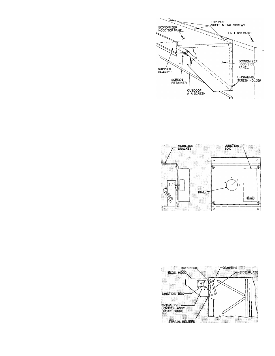
Fig. 4 — Economizer Outdoor Air Inlet
Hood Assembly
Fig. 5 — Enthalpy Control Assembly
Fig. 6 — Enthalpy Control Assembly
Installation Details