Fig. 19 — typical heat pump operation – Carrier 50EQ User Manual
Page 14
Attention! The text in this document has been recognized automatically. To view the original document, you can use the "Original mode".
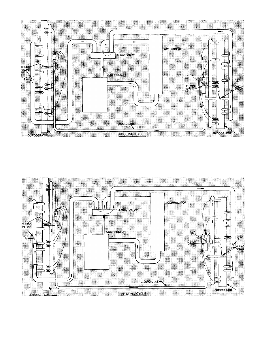
Hot gas from compressor flows thru the 4-way valve and is
directed to the outdoor coil header At the header it is condensed
and subcooled thru converging circuits (4-2-1) Refrigerant
leaves the outdoor coil by way of the check valve to the liquid
line
The refrigerant then flows thru the filter-drier and feeds the
indoor coil by way of capillary tubes on each circuit
Each circuit evaporates the refrigerant and the circuits are
combined in the indoor coil header with some of the circuits
flowing thru the check valve
The refrigerant then flows thru the 4-way valve accumulator
and back to the compressor
Hot gas from compressor flows thru the 4-way valve and is
directed to the indoor coil header At the header it is condensed
and directed thru subcooling circuits and out the indoor coil
check valve to the liquid line
The refrigerant then feeds the outdoor coil by way of a strainer
and then thru capillary tubes on each circuit
3. Each circuit evaporates the refrigerant and the circuits are
combined in the outdoor header with some of the circuits
flowing thru the check valve
4 The refrigerant then flows thru the 4-way valve, accumulator
and back to the compressor
t
NOTE: Refrigeration circuitry for cooling and heating cycle is shown for single system: 50EQ, with 2 individual and independent
refrigeration systems operates in identical fashion
Fig. 19 — Typical Heat Pump Operation
14