Fig. 15 — charging chart — cooling, 50eq034, 16 — heating cycle operation chart 50eq024 – Carrier 50EQ User Manual
Page 12
Attention! The text in this document has been recognized automatically. To view the original document, you can use the "Original mode".
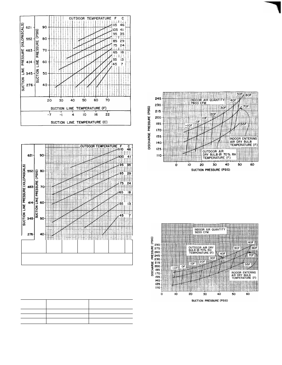
Fig. 14 — Charging Chart — Cooling,
50EQ028
3 3 41
Э
a
SUCTION
3
6C
-INE TEMP
7
ERATURE
0 e
(F)
0
-i 4 10 № 22 27
SUCTION LINE TEMPERATURE (C)
Fig. 15 — Charging Chart — Cooling,
50EQ034
Table 6 — Air Quantity Limits
UNIT
MINIMUM CFM
MAXIMUM CFM
50EQ
STANDARD AIR
STANDARD AIR
024
6,800
9,000
028
8,300
12,000
034
10,080
14,000
NOTES
1 Operation below minimum limits may cause a high
pressure condition when unit is on heating cycle
2 The operation of electric resistance heaters above 47 F
when compressor heat is operational is not recom
mended below minimum cfm's Field-adjustable ther
mostat in unit locks out electric heat
To check system operation during heating
cycle, use correct Heating Cyele Operation Check
Chart (Fig. 16, 17, or 18). This chart indicates
whether a correct relationship exists between sys
tem operating pressures and indoor and outdoor
entering air temperatures. If pressure and tem
perature lines do not intersect on chart, the system
refrigerant charge may not be correet or other sys
tem abnormalities may exist. Do not use Heating
Cycle Chart to adjust refrigerant charge.
Fig
16 — Heating Cycle Operation Chart
50EQ024
Fig. 17 — Heating Cycle Operation Chart —
50EQ028
t
t
12