Accurater® (bypass type) servicing — see, Refrigerant charging, A caution – Carrier 38HD User Manual
Page 9: Caution
Attention! The text in this document has been recognized automatically. To view the original document, you can use the "Original mode".
field repaired, therefore only a complete valve or valve
stem and service port caps are available for replacement.
AccuRater® (Bypass Type) Servicing
— See
Fig. 4 for bypass type AccuRater components. The piston
has a refrigerant metering hole through it. The retainer
forms a stop for the piston in the refrigerant bypass mode,
and a sealing surface for liquid line flare connection. To
check, clean or replace piston:
1. Shut off power to unit.
2.
Pump
unit
down
using
Pumpdown
Procedure
described previously.
3. Remove liquid line flare connection from AccuRater.
4. Pull retainer out of body, being careful not to scratch
flare sealing surface. If retainer does not pull out
easily, carefully use locking pliers to remove retainer.
5. Slide piston out by inserting a small soft wire, with
small kinks, through metering hole. Ensure metering
hole, sealing surface around piston cones and fluted
portion of piston are not damaged.
6. Clean piston refrigerant metering hole.
7.
Replace retainer 0-ring before reassembling bypass
type AccuRater. Carrier O-ring part number is
99CC501052.
Refrigerant Charging
A
CAUTION
To prevent personal injury, wear safety glasses and
gloves when handling refrigerant. Do not overcharge
system. This can cause compressor flooding.
A
CAUTION
Service valves must be fully backseated to close
service port. There is no Schrader valve at the service
port and failure to backseat the valve could result in
loss of system charge or personal injury.
To check and adjust charge during cooling season, use
Tables 4 and 5 and the following procedure:
1. Operate unit a minimum of 15 minutes before check
ing charge.
Measure suction pressure by attaching a gage to
suction valve service port.
Measure suction line temperature by attaching a
service thermometer to unit suction line near suction
valve. Insulate thermometer for accurate readings.
Measure outdoor coil inlet air dry-bulb temperature
with a second thermometer.
Measure indoor coil inlet air wet-bulb temperature
with a sling psychrometer.
Refer to Table 4. Find air temperature entering
outdoor coil and wet-bulb temperature entering
indoor coil. At this intersection note the superheat.
Refer to Table 5. Find superheat temperature and
suction pressure, note suction line temperature.
If unit has higher suction line temperature than
charted temperature, add refrigerant until charted
temperature is reached.
If unit has lower suction line temperature than
charted temperature, bleed refrigerant until charted
temperature is reached.
If air temperature entering outdoor coil or pressure
at suction valve changes, charge to new suction line
temperature indicated on chart.
This procedure is valid, independent of indoor air
quantity.
2
.
3.
4.
5.
6
.
7.
10
.
11
Table 4 — Superheat Charging Table
(Superheat Entering Suction Service Valve)
OUTDOOR
TEMP (F)
55
60
65
70
75
80
85
90
95
100
105
110
115
50
INDOOR COIL ENTERING AIR (F) WB
52
12
10
54
14
12
10
56
17
20
15
13
10
58
18
16
13
60 62
23 26
21 24
19 21
16
12
64
29
27
24
19 21
15
12
18
15
11
66
32
30
27
24
21
18
15
13
10
68
35 37
33
30
27
24
21
19
16
14
12
70 72
40
35 38
33 36
30 33
28 31
25 28
22
20
18 22
15
13
11
74
42 45
40
38
36
34
31
26
24
20
17
15
14
76
43
41
39
37
35
30
27
25
23
22
20
18
33
31
29
27
26
25
23
Do not attempt to charge system under these conditions or
refrigerant slugging may occur
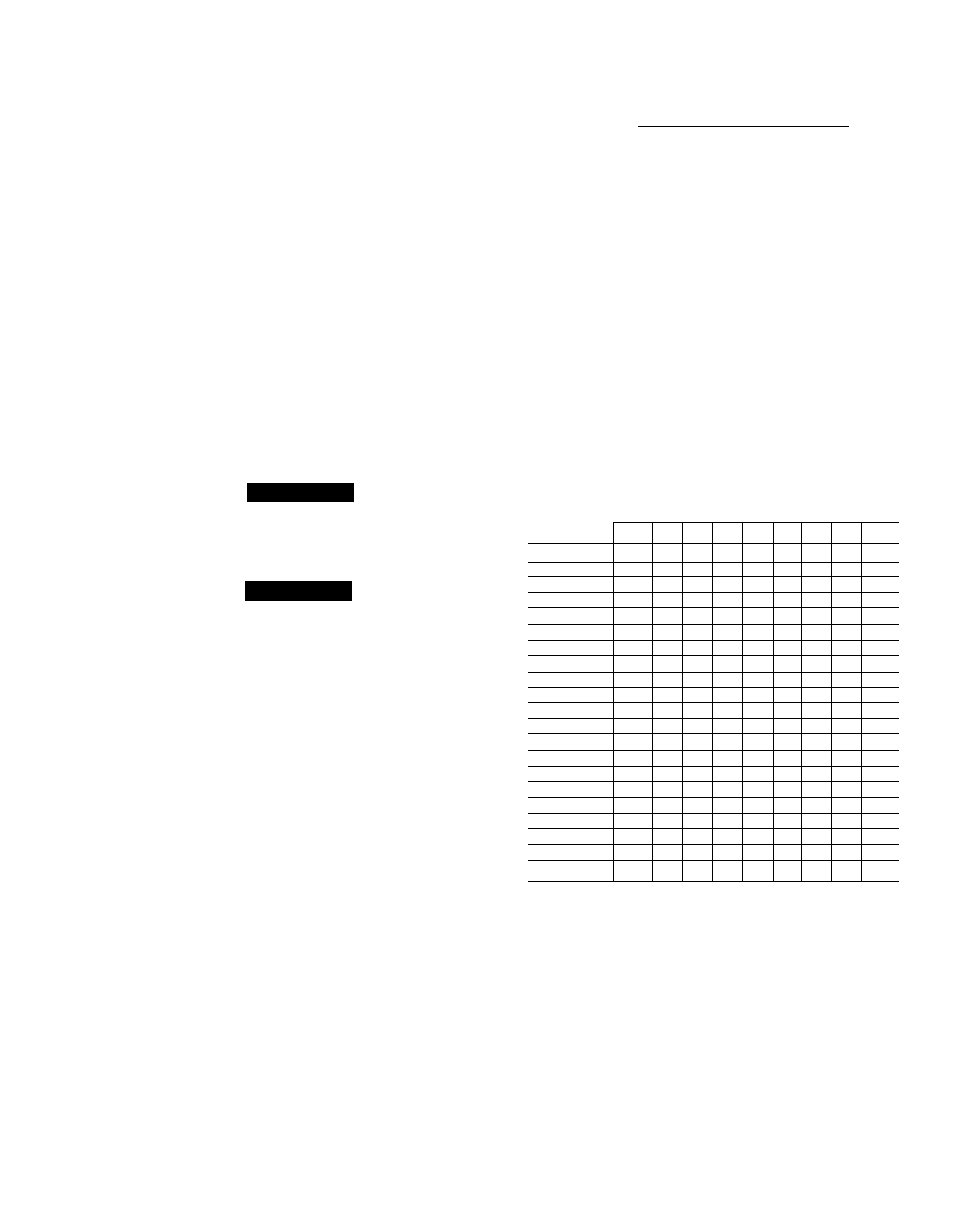
Table 5 — Required Suction-Tube Temperature (F)
(Entering Suction Service Valve)
TEMP (F)
61.5 64.2 67.1 70.0 73.0 76.0 79.2 82.4 85.7
0
35
37
39
41
43
45
47
49
51
2
37
39
41
43
45
47
49
51
53
4
39
41
43
45
47
49
51
53
55
6
41
43
45
47
49
51
53
55
57
8
43
45
47
49
51
53
55
57
59
10
45
47
49
51
53
55
57
59
61
12
47
49
51
53
55
57
59
61
63
14
49
51
53
55
57
59
61
63
65
16
51
53
55
57
59
61
63
65
67
18
53
55
57
59
61
63
65
67
69
20
55
57
59
61
63
65
67
69
71
22
57
59
61
63
65
67
69
71
73
24
59
61
63
65
67
69
71
73
75
26
61
63
65
67
69
71
73
75
77
28
63
65
67
69
71
73
75
77
79
30
65
67
69
71
73
75
77
79
81
32
67
69
71
73
75
77
79
81
83
34
69
71
73
75
77
79
81
83
85
36
71
73
75
77
79
81
83
85
87
38
73
75
77
79
81
83
85
87
89
40
75
77
79
81
83
85
87
89
91
Time Guard® II Device
— Accessory Time Guard
II device is shipped in 6-pack units. Apply it to Carrier
38HD units to protect the unit compressor from short
cycling. See Fig. 9. The device prevents short cycling by
providing a 5-minute delay (± 2 minutes) before restart
ing a compressor after shutdown for any reason. On
normal start-up, the 5-minute delay occurs before the
thermostat closes. After the thermostat closes, the Time
Guard 11 device then has a 3-second delay prior to
contactor closure.
INSTALLATION — Install the Time Guard II device in
the 24-v control circuit, locating it in the space provided
at the front of the control box, using the screws provided.