Service, A caution – Carrier 38HD User Manual
Page 8
Attention! The text in this document has been recognized automatically. To view the original document, you can use the "Original mode".
Charge System — Release holding charge into sys
tem by opening (backseating) liquid and suction line
service valves. Add charge amount as required for the
total system. See Table 1. For indoor sections not in
cluded in Table 1, see Refrigerant Charging.
To Start Unit — Assuring that crankcase heater has
been on for 24 hours, and field disconnect is closed, set
room thermostat below ambient. Unit compressor starts
after a 5-minute delay if equipped with optional Time
Guard® 11. Operate unit for 15 minutes, then check
system refrigerant charge. See Refrigerant Charging.
SERVICE
A
CAUTION
Before performing recommended maintenance, be
sure unit main power switch is turned off. Failure to
do so may result in electric shock or injury from
rotating fan blade.
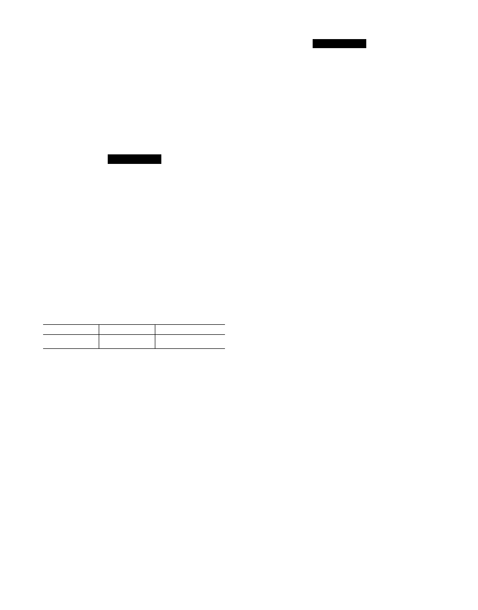
Condenser Fan is held by a reinforced wire mount
which clamps the fan motor in position. See Fig. 8 for
proper mounted fan position.
I 1
I I
I I
n I .
-FAN BLADE
T
OUTSIDE EDGE OF
FAN DECK
OUTSIDE EDGE
OF GRILLE
, Q a n a n a
Q Q f. a
DIMENSION FROM
OUTSIDE TOP EDGE OF
BLADE TO OUTSIDE EDGE
OF FAN DECK SEE
CHART BELOW
UNIT SIZE
38HD018
38HD024,030
38HD036,048,060
433" (11 mm)
709" (18 mm)
16" (4 mm)
Fig. 8 — Mounted Fan Positions
High Pressure Relief Valve is located in com
pressor. Relief valve opens at a pressure differential of
approximately 450 ± 50 psig between suction (low side)
and discharge (high side) to allow pressure equalization.
Internal
Current
and
Temperature
Sensitive
Overload resets automatically when internal com
pressor motor temperature drops to a safe level (over
loads may require up to 45 minutes to reset) When an
internal overload is suspected of being open, check by
using an ohmmeter or continuity tester. If necessary,
refer to Carrier Standard System Techniques Manual,
Chapter 2, for complete information.
Pumpdown Procedure — The system may be
pumped down in order to make repairs on low side with
out losing complete refrigerant charge.
1. Attach pressure gage to suction service valve gage
port.
2. Frontseat the liquid line valve.
3. Start unit and run until suction pressure reaches
5 psig (see Caution).
4. Shut unit off and frontseat suction valve.
5. Vent remaining pressure.
A
CAUTION
38HD unit coils hold only the factory designated
amount of refrigerant. Additional refrigerant may
cause units to relieve pressure through internal
pressure relief valve (indicated by a sudden rise of
suction pressure) before suction pressure reaches
5 psig. if this occurs, shut off unit immediately,
frontseat suction valve and vent remaining pressure.
Filter Drier — Whenever the moisture-liquid indicator
shows presence of moisture, replace filter drier. Refer to
Carrier Standard Service Techniques Manual, Chapter 1,
Refrigerants, for details on servicing filter driers.
High -Pressure Switch — This switch, located on
discharge line, protects against high discharge pressures
caused by such events as overcharge, condenser fan motor
failure, system restriction, etc. It opens on pressure rise at
about 426 psi. If system pressures go above this setting
during abnormal conditions, switch opens. Do not
attempt to simulate these system abnormalities, as high
pressures pose a serious safety hazard. High-pressure
switch is also checked with an ohmmeter similar to cheek
ing low-pressure switch. If system pressure is below
426 psi, switch shows continuity. It is replaced in same
manner as low-pressure switch. Observe all safety
precautions.
Low-Pressure Switch — This switch, mounted on
the suction line, has fixed nonadjustable settings.
TO CHECK — Attach pressure gage to suction service
valve gage port. Slowly close liquid shutoff valve and
allow compressor to pump down. Do not allow com
pressor to pump down below 2 psig (13.8 kPa). Com
pressor should shut down when suction pressure drops to
cutout pressure in Table 2, and should restart when
pressure builds up to cut-in pressure shown after CLO
(Compressor Lockout) has been reset and optional Time
Guard has completed its timing cycle.
Crankcase Heater prevents refrigerant migration and
compressor oil dilution during shutdown when com
pressor is not operating. If crankcase heater is de
energized for more than 6 hours, both compressor service
valves must be closed.
Crankcase heaters come in 2 basic types; wraparound
(bellyband) type that is wrapped externally around com
pressor shell, and insertion type that is inserted into
compressor oil well in shell of compressor. Both types
are in this family of units.
Crankcase heater is powered by high-voltage power of
unit. It is connected across the line side of the contactor
and operates eontinually. Use extreme caution trouble
shooting this device with power on. Easiest method of
troubleshooting is to apply voltmeter across crankcase
heater leads to see if heater voltage is on. Do not touch
heater. Carefully feel area around crankcase heater. If
warm, crankcase heater is probably functioning. With
power off, and heater leads disconnected, check across
leads with ohmmeter. Do not look for a specific resistance
reading. Check for resistance or an open circuit. Change
heater if an open circuit is detected.
Service Valves — The service valves in the condensing
unit come from the factory frontseated This means the
refrigerant charge is isolated from the line set connec
tion ports. To prevent damage to the valve, use a wet cloth
or other accepted heat sink material on the valve before
brazing.
The service valves must be backseated (turned counter
clockwise until seated) before the service port caps can be
removed and hoses of gage manifold connected. In this
position,
refrigerant
has
access
from
and
through
outdoor and indoor unit. The service valve cannot be