Fig. 6 — typical control circuit connections, A warning – Carrier 38HD User Manual
Page 6
Attention! The text in this document has been recognized automatically. To view the original document, you can use the "Original mode".
________I
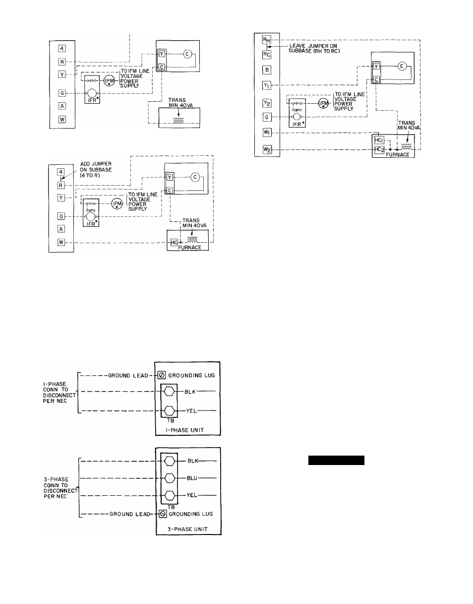
ARRANGEMENT A-(COOLING ONLY)
ARRANGEMENT B-ONE TRANSFORMER
(COOLING AND ONE-STAGE HEATING)
ARRANGEMENT C-ONE TRANSFORMER
(COOLING AND TWO-STAGE HEATING)
*IFR and IFM are located in furnace on heating-cooling applica
tions If accessory IFR is required for cooling-only applications,
locate (IFR) in fan coil
C
—
HC
-
IFM
—
IFR
—
Trans —
Contactor (12-va)
Heating Control
Indoor Fan Motor
Indoor Fan Relay
Transformer
____ —. Field Wiring
- Factory Wiring
NOTE Refer to unit wiring label for wire colors C t o G a n d C t o Y
connections
f
Fig. 6 — Typical Control Circuit Connections
CONTROL CIRCUIT WIRING — Control voltage is
24 volts (40 va minimum). See Fig. 6 and unit label
diagram for field-supplied wiring details. Route control
wires through opening in unit side panel to connection in
unit control box.
TB — Terminal Board
— O
------ TB Connections
Field Wiring
Factory Wiring
NOTE; For wire runs up to 50 ft, use no. 18 AWG insu
lated wire (35 C minimum). For 50 to 75 ft, use no. 16
AWG insulated wire (35 C minimum). For over 75 ft, use
14 AWG insulated wire (35 C minimum).
NOTE: Operation of unit on improper line voltage con
stitutes abuse and could affect Carrier warranty See
Table 3. Do not install unit in system where voltage may
fluctuate above or below permissible limits.
See Table 3 for recommended fuse sizes. When making
electrical connections, provide clearance at unit for refrig
erant piping connections
Use furnace oi fan coil transformer as 24-v (40-va
minimum) supply for system as shown in Fig. 7 or use
accessory transformer.
A
WARNING
To avoid personal injury, be sure indoor blower has
stopped before attempting service or maintenance.
Operating voltage to compressor must be within
voltage range indicated on unit nameplate. On 3-phase
units voltages between phases must be balanced within
2% U se the following formula to determine the % voltage
imbalance.
% Voltage Imbalance
max voltage deviation frqm average voltage
Fig. 7 — Line Power Connections
100
X
average voltage