A caution, Step 4 — complete electrical connections, Caution – Carrier 38HD User Manual
Page 5
Attention! The text in this document has been recognized automatically. To view the original document, you can use the "Original mode".
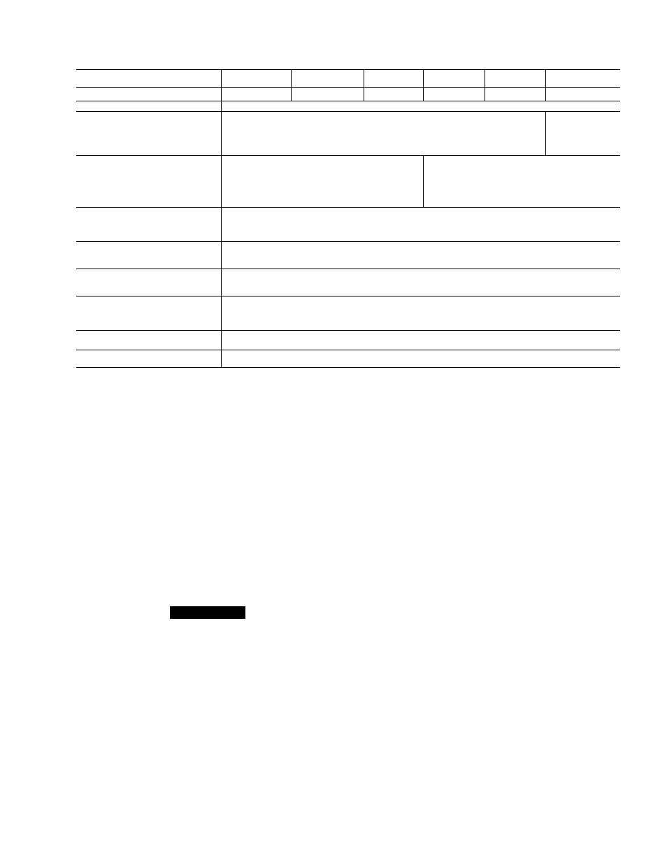
Table 2 — Physical Data
UNIT 38HD
018
024
030
036
048
060
OPER WT (lb), 1 ph/3 ph
148/*
160/*
171/*
240/226
244/235
244/235
REFRIGERANT
R-22
COMPRESSOR
Model
Oil (pts), initial/recharge
Crankcase Heater Watts
Hermetic
Tecumseh
I
Tecumseh | Carlyle I Carlyle I Carlyle
AW5519 AW5524 J30 | J36 | J48
32/30 32/30 46/44
40
Copeland
CRP5-0450
70/66
CONDENSER AIR FAN
Number — Rpm
Diameter (in.) — no. blades
Fan Pitch
Motor Hp (NEMA)
Nominal Cfm
Propeller, C
1 —
18 — 3
25
1
27
Vs
1835
1
1720
1
1750
)irect Drive
850
24 — 3
24
'A
3900
¿ONDENSER COIL
Rows
Face Area (sq ft)
Fins/in.
1
'/2 1
2 2
1
2
1
2
6 1
1
12.3
15
CONNECTIONS
Suction (in.), Sweat
Liquid (in.). Flare
% 1 % 1 %
%
LINE SIZES
Suction
Liquid
% %
1’/a
%
CONTROLS
Pressurestat Settings
ui_u Cutout
Cut-in
426 ± 7
320 ± 20
1
Cutout
Cut-in
7 ± 5
22 ± 5
FUSIBLE PLUG
210F
*Not applicable
should be installed just after liquid line shutoff valve.
Do not use a receiver (a receiver is not provided with unit
and one should not be used).
MAKE PIPING SWEAT CONNECTIONS — Remove
plastic caps from liquid and suction service valves.
Use refrigerant grade tubing. Service valves are closed
from the factory and ready for brazing. After wrapping
the service valve with a wet cloth, the tubing set can be
brazed to the service valve using either silver bearing or
non-silver bearing brazing material. Consult local code
requirements. Refrigerant tubing and indoor coil are now
ready for leak testing.
NOTE: Unit is shipped with R-22 factory holding charge
indicated on nameplate.
Pass nitrogen or other inert gas through piping while
brazing to prevent formation of copper oxide.
A
CAUTION
To avoid damage while brazing, service valves should
be wrapped with a heat-sinking material such as a wet
cloth.
PROVIDE SAFETY RELIEF — A fusible plug is
located in unit suction line. Do not cap this plug. If local
code requires additional safety devices, install as directed.
Step 4 — Complete Electrical Connections
POWER WIRING — Unit is factory wired for voltage
shown on nameplate. Provide adequate fused disconnect
switch within sight of unit, readily accessible, but out of
reach of children. Provision for locking switch open (off)
is advisable to prevent power from being turned on while
unit is being serviced. Disconnect switch, fuses, and field
wiring must comply with National Electrical Code and
local code requirements. Use copper wire only between
disconnect switch and unit. Use minimum 60 C wire for
field power connection.
Route power wires through opening in unit side panel
and connect in unit control box as shown on unit label
diagram and Fig. 6. Unit must be grounded