Step 2 — rig and mount unit, A caution, Caution – Carrier 38HD User Manual
Page 4
Attention! The text in this document has been recognized automatically. To view the original document, you can use the "Original mode".
RETAINER
FLARE NUT
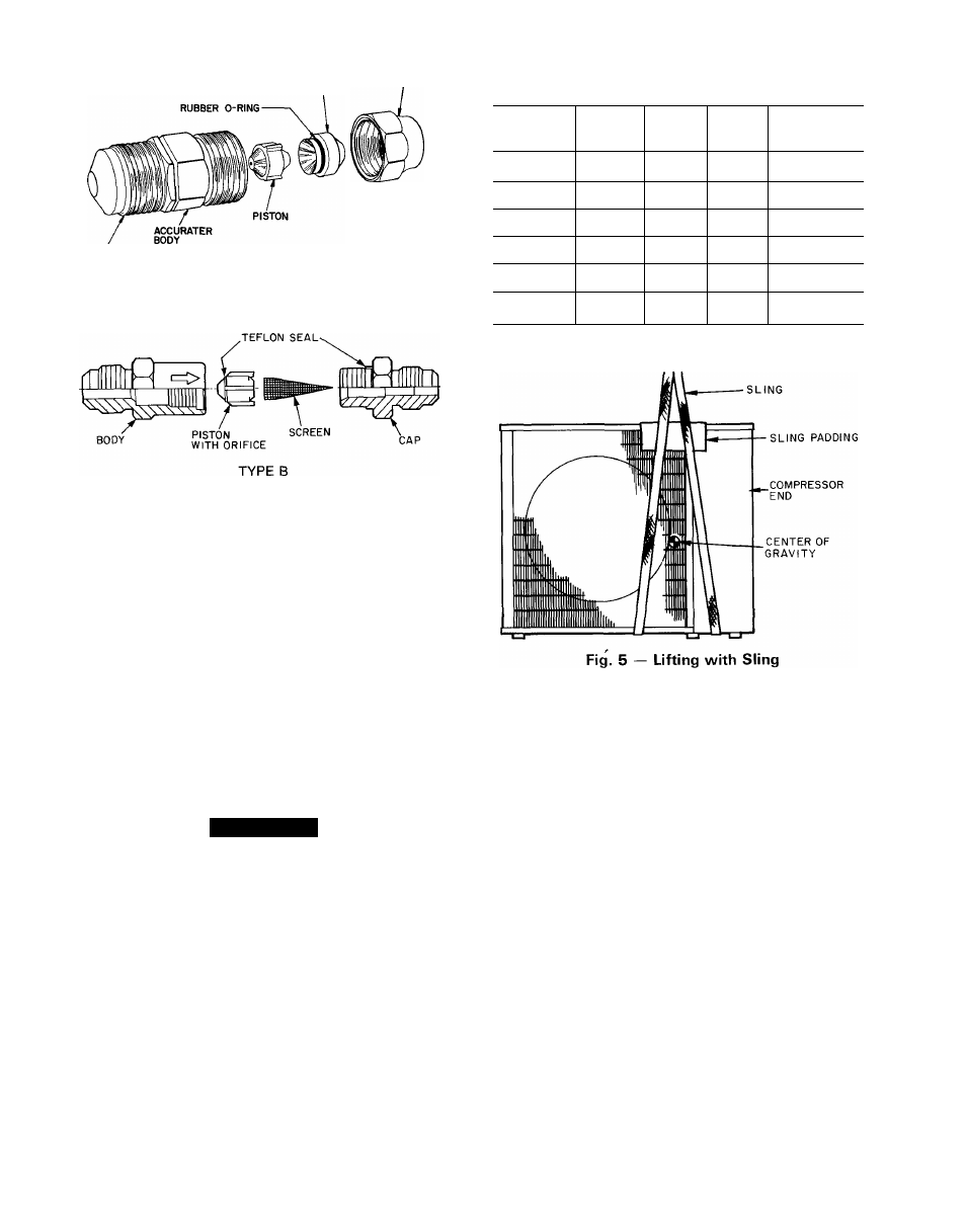
Table 1 — AccuRater Optimization Chart
FLARE
CONNECTION
TYPE A
(Arrow on AccuRater body points in
metering
direction.)
(Arrow on AccuRater body points in
free flow
direction.)
Fig. 4 — AccuRater® (Bypass Type) Components
Step 2 — Rig and Mount Unit
MOUNTING ON GROUND — Mount on a solid, level,
concrete pad Position unit so water or ice from roof
cannot drop directly onto unit. Stacking Kit 38H D900031
and -041 are available where such application is required.
See instructions provided with accessory kit. If conditions
or local codes require unit be fastened to pad, tiedown
bolts should be used and fastened through slots provided
in unit mounting feet.
MOUNTING ON ROOF
or frame.
Mount on a level platform
RIGGING
A
CAUTION
Be sure unit panels are securely in place prior to
rigging.
Keep unit upright. Lift unit using sling. Use cardboard
or padding under sling, and spreader bars to prevent sling
damage to unit. See Fig. 5. See Fig. 2 and 3 for center of
gravity reference. Install unit so that coil does not face
into prevailing winds. If this cannot be done, and constant
winds above 25 mph are expected, use Accessory Wind
Baffle, Part Number 38QR900041 or -051. See instruc
tions provided with accessory kit
Step 3 — Complete Refrigerant Piping Con
nections — Condensing units may be connected to
evaporator sections using field-supplied tubing of refrig
erant grade, correct size and condition. See Table 2.
Do not use less than 10 ft of interconnecting tubing and
do not bury more than 3 ft of line set undergrouiid. If any
section is buried, there must be a 6-in. vertical rise to the
valve connections on the outdoor unit
OUTDOOR
UNIT
INDOOR
UNIT
INDOOR
PISTON
PISTON
TYPE
REQUIRED
SYSTEM
CHARGE (lb)
38HD018
28RD024
40HD024
_
A
B
—
38HD024
28RD030
40HD024
61
A
B
55
38HD030
28RD043
40HD036
70
A
B
5 7
38HD036
28RD043
40HD036
73
A
B
11.5
38HD048
28RD049
40HD048
86
A
B
97
38HD060
28RD061
40HD060
88
A
B
11 2
If more than the recommended length is buried, refrig
erant may migrate to cooler buried section during
extended periods of unit shutdown. This causes refrig
erant slugging and possibly compressor damage at
start-up.
When more than 50 ft of interconnecting tubing and
more than 30 ft vertical lift is used, consider the amount of
liquid lift, and compressor oil return See Part 3 of Carrier
System Design Manual for design details, or contact your
local Distributor
If either refrigerant tubing or indoor coil is exposed to
atmospheric conditions for longer than 5 minutes, it must
be evacuated to 1000 microns to eliminate contamination
and moisture in the system.
Run refrigerant tubes as directly as possible, avoiding
unnecessary turns and bends. Suspend refrigerant tubes
so they do not damage insulation on vapor tube and do
not transmit vibration to structure Also, when passing
refrigerant tubes through wall, seal opening, so vibration
is not transmitted to structure. Leave some slack in refrig
erant tubes between structure and unit to absorb vibra
tion Refer to evaporator installation instructions for
additional information.
USE
FILTER
DRIER
AND
MOISTURE
INDI
CATOR — The filter drier is factory supplied. Moisture
indicator (sight glass) is a field-supplied option and