100 x – Carrier 38AK024-044 User Manual
Page 6
Attention! The text in this document has been recognized automatically. To view the original document, you can use the "Original mode".
4. Maximum field wire sizes allowed by lugs on terminal
block are:
350 MCM for models 38AK028 (208/230-3-60),
38AK034 (208/230-3-60, 230-3-50), and
38AK044 (208/230-3-60, 230-3-50)
2/0 AWG for all other models.
5. Terminals for field power supply are suitable for
copper, copper-clad aluminum or aluminum conduc
tors. Insulation must be rated 167 F (75 C) minimum.
CONDENSER FANS — The fans must rotate counter
clockwise when viewed from above. If necessary, correct
direction of fan rotation by interchanging any 2 power
input wires at disconnect switch. Affix crankcase heater
decal (located in installer’s packet) to unit disconnect switch.
FIELD CONNECTIONS
1. Main Power — Bring wires from the fused disconnect
switch through hole in bottom rail of unit to control
box (Fig. 6, 7, 8) and connect terminals 1 1 1 1 ,
[12
1 3 on line side of terminal block TBl (see Fig. 9).
To comply with NEC Article 440-14, the disconnect
must be located within sight from and readily acces
sible from unit.
■ 2. 24-v Control Power — Units have single point power
connections. Control circuit is directly connected inter
nally to unit. Maximum 24-v control circuit is 3 amps.
NOTE: For wire runs up to 50 ft. use no. 18 AWG
insulated wire (35 C min.). For 50 to 75 ft., use no. 16
AWG insulated wire (35 C min.). For over 75 ft. use 14
AWG insulated wire (35 C min.).
3. Control Circuit Interlock — An airflow switch may be
installed in the indoor air handler to prevent unit from
running when indoor air is not flowing. This switch (no.
HR81JE001) is available from Service Parts Center, or
equivalent can be field supplied. This should be electri
cally interlocked in the control circuit, between term
inals I 1 I and I 6 I (for flow switch) on TB2. See Fig.
9 for field wiring. This is in the 115-v circuit. Wires must
be run in conduit with ground wire.
4. Transformer Connections — See unit wiring label dia
gram, notes 1 and 2, located behind compressor com
partment end access door.
IMPORTANT: Ensure power to the crankcase
heater is always on (except when servicing the unit).
If circuit breakers inside unit shut down the com
pressor and condenser fans, crankcase heater
remains on.
UNBALANCED 3-PHASE SUPPLY VOLTAGE —
Never operate a motor where a phase imbalance in supply
voltage is greater than
2%.
Use the following formula to
determine the
%
voltage imbalance:
% Voltage Imbalance
max voltage deviation from average voltage
I ^
= 100 X
average voltage
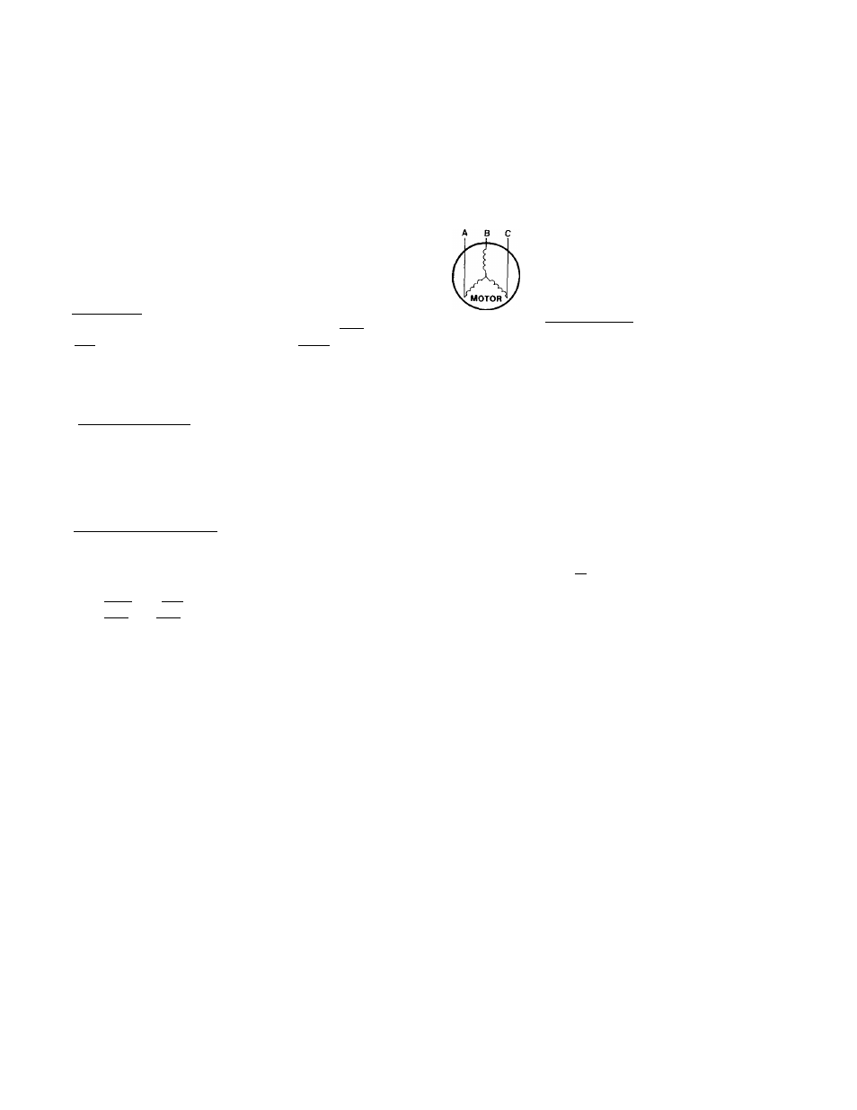
Example: Supply voltage is 240-3-60.
AB = 243 volts
BC = 236 volts
AC = 238 volts
Average Voltage =
243 + 236 + 238 = 239 volts
Determine maximum deviation from average voltage:
(AB) 243 - 239 = 4 volts
(BC) 239 - 236 = 3 volts
(AC) 239 - 238 = 1 volt
Maximum deviation is 4 volts. Determine
%
voltage
imbalance:
% Voltage Imbalance = 100 x —^ = 1.7%
239
This amount of phase imbalance is satisfactory as it is
below the maximum allowable 2%.
IMPORTANT: Contact your local electric utility
company immediately if the supply voltage phase
imbalance is more than 2%.