Carrier 38AK024-044 User Manual
Page 13
Attention! The text in this document has been recognized automatically. To view the original document, you can use the "Original mode".
OR DIA HOLE
[92 I] 3 5/8"
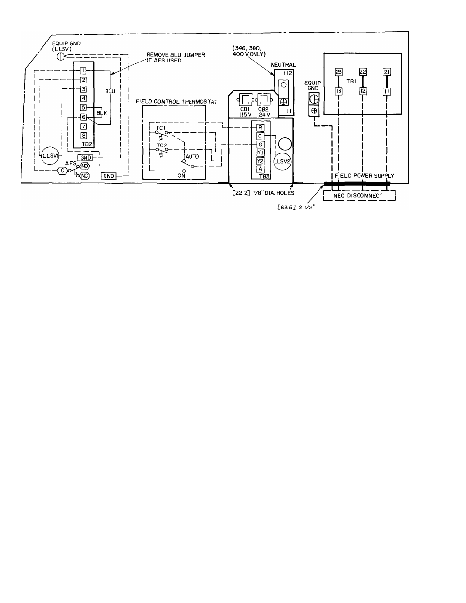
NOTES:
1
Factory wiring in accordance with National Electricai Code ( N E C ) Any fieid modifications or additions must be in
compliance with aii appiicabie codes
2 AM field interlock contacts in the 115-y control circuit must have minimum rating of 180 va pilot duty pi us capacity required
for field-installed equipment All field interlock contacts in the 24-v control circuit must have minimum ratingof TOvapilot
duty plus capacity required for field-installed equipment Remove wire between terminals TB2-1 and 6 when airflow
switch is field installed
3 For internal unit wiring, reference wiring book TB2 is 115-1-60, TB3 is 24-1-60
LEGEND
AFS
— Airflow Switch
GND
— Ground
LLSV1
— Liquid Line Solenoid Valve for Pumpout
LLSV2
— Liquid Line Solenoid Valve for Capacity Control
TB
— Terminal Block
_ — — — Field Power Wiring
________ Field Control Wiring
________ Factory Installed Wiring
Fig. 9 — Typical Wiring Schematic
10