Carrier 38AK024-044 User Manual
Page 21
Attention! The text in this document has been recognized automatically. To view the original document, you can use the "Original mode".
Fan Adjustment (See Fig. 16)
TOP OF FAN ORIFICE
FILL HOLE IN FAN HUB
WITH PERMAGUM
FAN BLADE
ORIFICE
FAN SHAFT
HUB PLATE
PROP LOCATION
“A” in (mm)
Min.
Max.
60 Hz
36AK024
3
.
12
(
79
.
2
)
3.38 (85.9)
38AK028-034
38AK044
3.62(91.9)
3.88 (98.6)
50 Hz
38AK024
38AK028,034,044
3.62(91.9)
3.12(79.2)
3.88 (98.6)
338(85.9)
Fig. 16 — Location of Prop on Motor Shaft
from Outside of Orifice Ring
Oil Charge — Compressors are factory charged with oil
as follows:
COMPRESSOR
AMOUNT
pints (liters)
06E4250
14(6.6)
06E9265
19(9.0)
06E9275
19(9.0)
06E9299
19(9.0)
When additional oil or a complete charge is required, use
only Carrier-approved compressor oil:
Witco Chemical Corp....................................... Suniso 3GS
Texaco, Inc................................................... Capella WF-32
Shrieve Chemical Co..........................Zerol 150 (Synthetic)
IMPORTANT: Do not use drained oil or use oil that
has been exposed to atmosphere. Refer to Carrier
Standard Service Techniques Manual, Chapter 1,
Refrigerants, for procedures to add or remove oil.
Liquid Shutoff/Charging Valve is located inside the
compressor compartment and is provided with 1/4-in. flare
connection for field charging.
Capacity Control is by either one or 2 suction pressure
actuated unloaders. Each controls 2 cylinders. Unloaders
are factory set (see Table 1) but may be field adjusted.
Number 1 unloader is on cylinder bank on same side of
compressor as terminal box.
CONTROL SET POINT — The control set point (cylinder
load point) is adjustable from 0 to 85 psig. To adjust, turn
control set point adjustment nut (Fig. 17) clockwise to its
bottom stop. In this position, set point is 85 psig. Then, turn
adjustment counterclockwise to desired control set point.
Every full turn counterclockwise decreases set point by 7.5
psig.
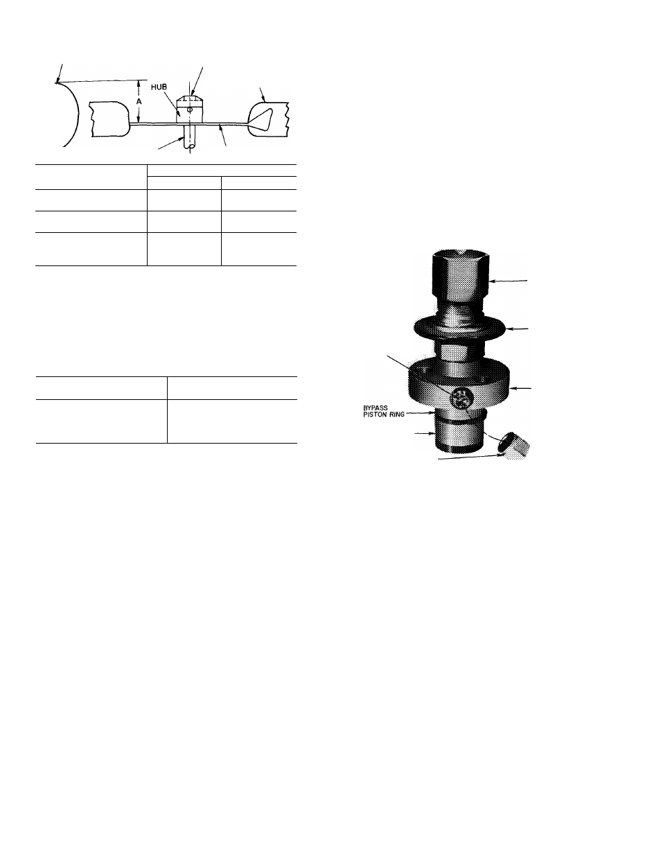
CONTROL
SET POINT
ADJUSTMENT
NUT
PRESSURE
DIFFERENTIAL
ADJUSTMENT
SCREW
POWER HEAD
VALVE BODY
BYPASS PISTON
DIFFERENTIAL SCREW -
SEALING CAP
(CAP MUST BE REPLACED
TO PREVENT REFRIGERANT LEAKAGE)
Fig. 17 — Capacity Control Valve
PRESSURE DIFFERENTIAL—The pressure differenti^
(difference between cylinder load and unload points) is
adjustable from 6 to 22 psig. To adjust, turn pressure
differential adjustment screw (Fig. 17) counterclockwise to
its backstop position. In this position, differential is 6 psig.
Then, turn adjustment clockwise to desired pressure differ
ential. Every full turn clockwise increases differential by 1.5
psig.
18