Carrier 38AK024-044 User Manual
Page 5
Attention! The text in this document has been recognized automatically. To view the original document, you can use the "Original mode".
Power Supply — Electrical characteristics of available
power supply must agree with unit nameplate rating. Supply
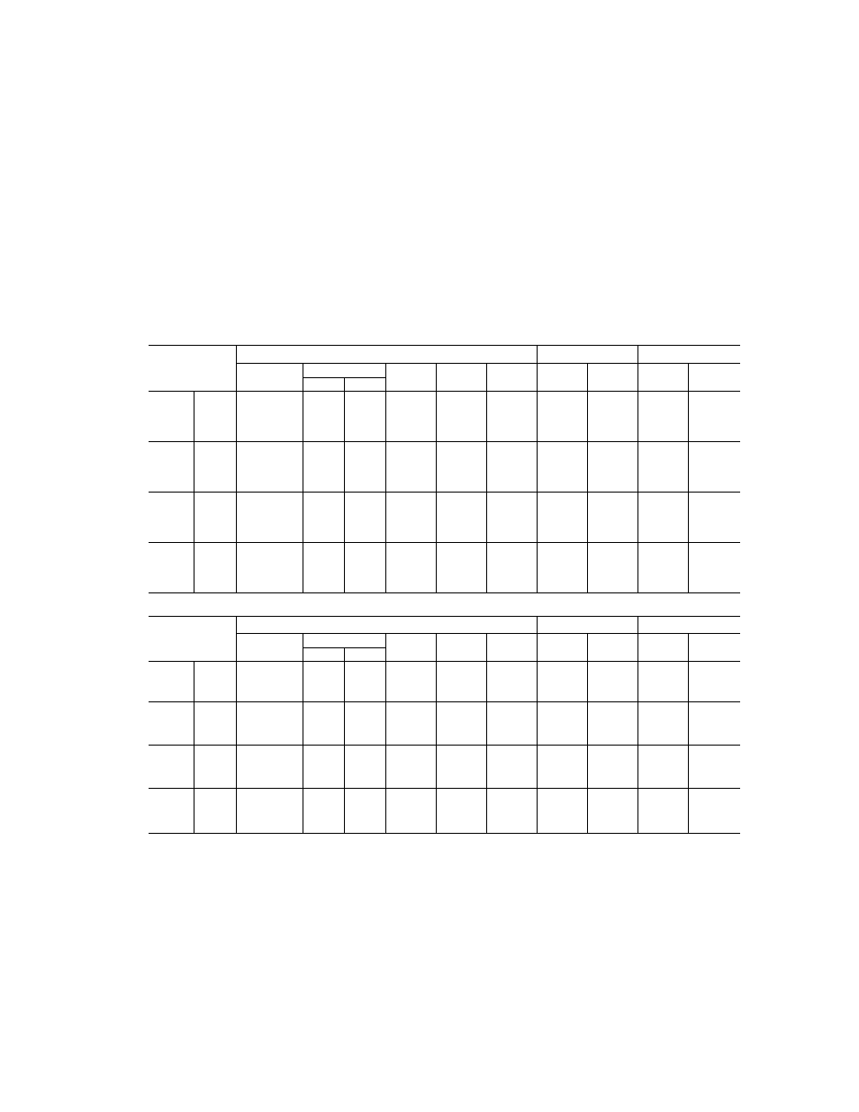
voltage must be within limits shown in Table 3.
IMPORTANT: Operating unit on improper supply
voltage, or with excessive phase imbalance, constitutes
abuse and may affect Carrier warranty. See Unbal
anced 3-Phase Supply Voltage, page 6.
Power Wiring — All power wiring must comply with
applicable local and national codes. Install field-supplied
branch circuit fused disconnect(s) per NEC (National Electri
cal Code) of a type that can be locked OFF or OPEN.
Disconnect(s) must be within sight from and readily acces
sible from unit in compliance with NEC Article 440-14.
GENERAL WIRING NOTES
1. A crankcase heater is wired in the control circuit so it is
always operable as long as power supply disconnect is
on, even if any safety device is open or unit stop-start
switch is off. It is protected by a 5-amp circuit breaker in
control power.
2.
The power circuit field supply disconnect should never be
open except when unit is being serviced or is to be down for a
prolonged period When operation is resumed crankcase
heater should be energtedfor 24 hours before start-up. If unit
is to be shut down for a prolonged period it is recommended
that the suction arid discharge valves be closed to prevent an
excessive accumulation of refrigerant in the compressor oil
3. Power entry is at one end only.
Table 3 — Electrical Data
60 HERTZ
UNIT
COMPRESSOR
FAN MOTORS!
MODEL
OfiAtr
Volts
SuDolied*
MCA
MOCP
ICF
RLA
LRA
FLA (ea)
Qty
3 Ph, 60 Hz
Min.
Max.
(Fuse)
500
208/230
187
254
92.1
150
348.6
68
345
3.6
2
024
200
380
342
418
51 1
80
194.9
346
191
3.9
2
600
460
414
508
46.9
80
1748
34 7
173
1 8
2
100
575
518
632
42.9
70
123.4
28.9
120
3.4
2
500
208/230
187
254
124.6
200
452.2
89.8
446
6.2
2
028
200
380
342
418
64.7
110
250.9
45.5
247
3.9
2
600
460
414
508
60 7
100
226.1
43.6
223
31
2
100
575
518
632
52.5
80
167.4
36.5
164
3.4
2
500
208/230
187
254
145 5
250
512.2
106.5
506
6.2
2
034
200
380
342
418
72.5
125
283.9
52.6
280
3.9
2
600
460
414
508
687
110
256.1
50
253
3.1
2
100
575
518
632
54.9
90
179.4
38.5
176
3.4
2
500
230
187
254
2030
350
702.4
147 5
690
62
3
044
200
380
342
418
111 1
175
3898
79.5
382
39
3
600
460
414
508
91 0
150
351 2
65.4
345
3.1
3
100
575
518
632
81.5
125
282.8
57.1
276
3.4
3
50 HERTZ
UNIT
COMPRESSOR
FAN MOTORS!
MODEL
38AK
Volts
Supplied*
MCA
MOCP
ICF
RLA
LRA
FLA (ea)
Qty
3 Ph, 50 Hz
Min.
Max.
(Fuse)
800
230
198
254
88.1
125
256.4
60.3
250
6.4
2
024
300
346
311
380
50.5
80
2044
333
200
44
2
900
400
342
400
49.3
80
1740
347
173
1.0
2
800
230
198
254
109
175
348.4
76.9
342
64
2
028
300
346
311
380
64.9
100
263.4
44.9
259
4.4
2
900
400
342
400
605
100
226.0
436
223
30
2
800
230
198
254
1202
200
372.4
859
366
6.4
2
034
300
346
311
380
76.1
125
2984
539
294
4.4
2
900
400
342
400
68.5
110
2560
50.0
253
3.0
2
800
230
198
254
1506
250
5578
105.1
545
6.4
3
044
300
346
311
380
112.6
175
408.8
79.5
400
4.4
3
900
400
342
400
90.8
150
351 0
65.4
345
30
3
FLA
— Full Load Amps
ICF
— Maximum Instantaneous Current Flow during starting (the
point in the starting sequence where the sum of the LRAfor
the starting compressor, plus the total RLA for all running
compressors, plus the total FLA for all running fan motors
is maximum).
LRA
— Locked Rotor Amps
MCA
— Minimum Circuit Amps (complies with National Electrical
Code [NEC], Section 430-24)
MOCP
— Maximum Overcurrent Protection
RLA
— Rated Load Amps
* Units are suitable for use on electrical systems where voltage
supplied to unit terminals is not below or above listed minimum and
maximum limits
t All fans are protected by a single circuit breaker.