Carrier 38AK024-044 User Manual
Page 4
Attention! The text in this document has been recognized automatically. To view the original document, you can use the "Original mode".
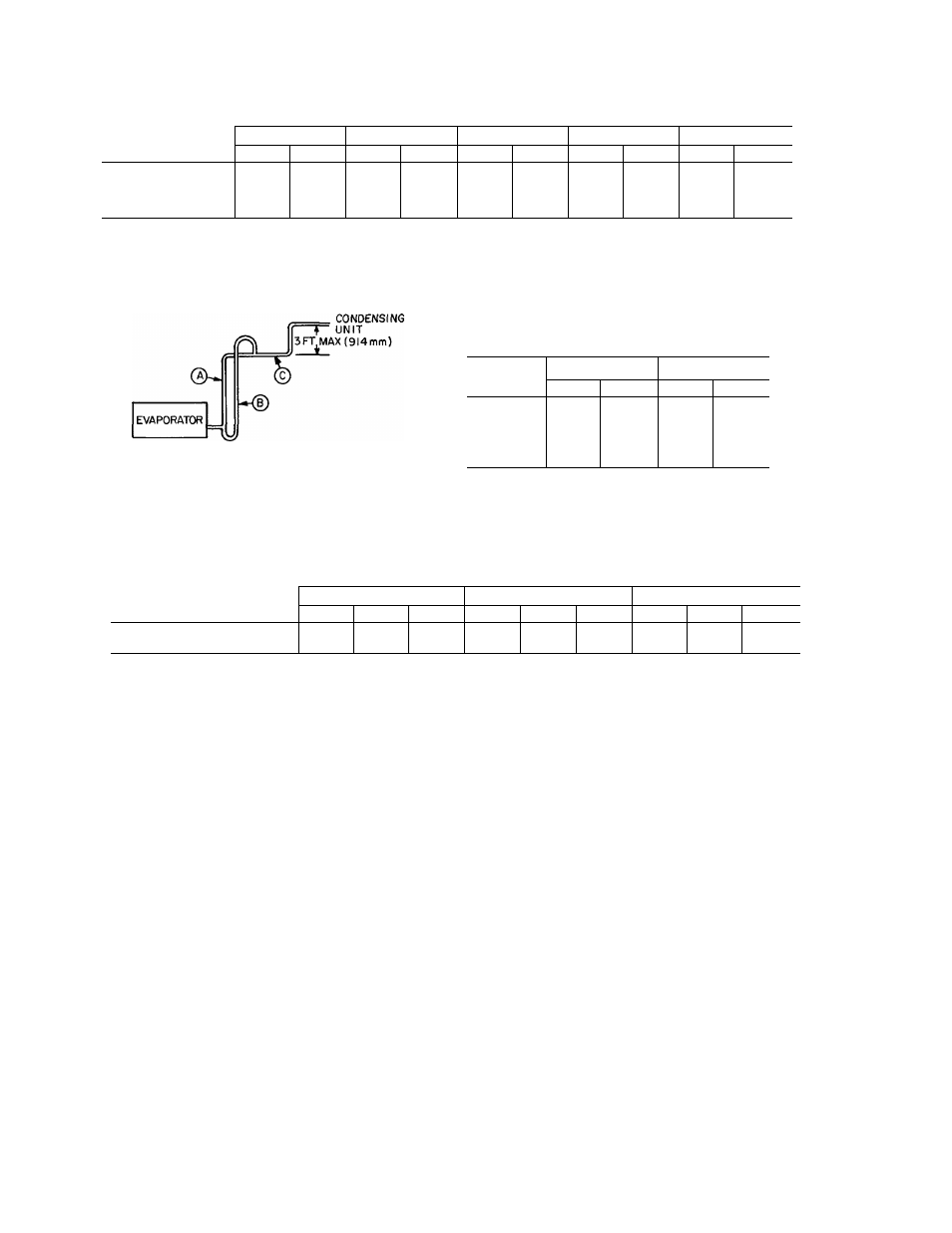
Table 2 — Refrigerant Piping Sizes
SINGLE SUCTION RISERS
LENGTH OF INTERCONNECTING PIPING (FT)
MODEL
38AK
16-25
26-50
51-75
76-100
101-200
L
S
L
S
L
S
L
S
L
S
024
5/8
1-5/8
7/8
1-5/8
7/8
2-1/8
7/8
2-1/8
7/8
2-1/8
028
7/8
1-5/8
7/8
2-1 /8
7/8
2-1/8
7/8
2-1/8
7/8
2-1/8
034
7/8
2-1 /8
7/8
2-1/8
7/8
2-1/8
1-1 /8
*
1-1/8
*
044
7/8
2-1/8
7/8
2-1/8
1-1/8
*
1-1/8
*
1-1/8
*
L-Liquid Line
S-Suction Line
* IMPORTANT
— Requires a double suction riser, see below:
NOTE: Liquid and suction iine sizes are OD (in)
(
a
) - SUCTION RISER WITHOUT TRAP
(
b
) - SUCTION RISER WITH TRAP
(^- SUCTION LINE TO CONDENSING UNIT
MAXIMUM LIQUID LIFT
UNIT 38AK
60 Hz
50 Hz
Ft
M
Ft
M
024
86
26
72
21
028
76
23
66
20
034
67
20
60
18
044
76
23
66
20
DOUBLE SUCTION RISERS
LENGTH OF INTERCONNECTING PIPING (FT)
MODEL
51-75
76-100
101-200
38AK
A
B
C
A
B
C
A
B
C
034
044
2-1/8
1-5/8
2-5/8
1-5/8
1-5/8
2-1/8
2-1/8
2-5/8
2-5/8
1-5/8
1-5/8
2-1/8
2-1/8
2-5/8
2-5/8
NOTE: A, B, C dimensions relate to reference diagram
SUCTION PIPING AT EVAPORATOR AND TXV
BULB LOCATION (See Fig. 5)
The purpose of these recommendations is to achieve good
mixing of the refrigerant leaving the evaporator suction
header for proper sensing by the TXV bulb.
1. A minimum of two 90° elbows must be installed
upstream of the expansion valve bulb location.
2. The TXV sensing bulb should be located on a vertical
riser where possible. If a horizontal location is neces
sary, secure the bulb at approximately the 4 o’clock
position.
3. Size the suction line from the evaporator through the
riser for high velocity. Enter the suction pipe sizing charts
in the Carrier System Design Manual at design tons and
equivalent length (for 2 degree F loss). If reading falls
between 2 sizes on chart, choose the smaller pipe size.
Suction piping for the high velocity section should be
selected for about 0.5 degree F friction loss. If a 2 degree
F loss is allowed for the entire suction line, 1.5 degree F
is left for the balance of the suction line and it should be
sized on that basis. Check that the high-velocity sizing is
adequate for oil return up the riser.
If an oil return connection at the bottom of this
suction header is supplied with an evaporator, this
connection must be teed-in ahead of first mixing elbow.
When the compressor is below the evaporator, the riser
at the evaporator does not have to extend as high as the
top level. After a 15-diameter riser has been provided,
the suction line may elbow down immediately.
SAFETY RELIEF — A fusible plug is located on unit
liquid line before the liquid valve.