Field control wiring, Low ambient compressor lockout(fig. 13) – Carrier 50DF034 User Manual
Page 9
Attention! The text in this document has been recognized automatically. To view the original document, you can use the "Original mode".
f
Field Control Wiring
STANDARD UNIT (WITHOUT ENERGY MANAGE
MENT ACCESSORY) — Install a Carrier-approved
accessory electronic thermostat on a subbase (or a trans
mitter on subbase if remote sensor is used) per installation
instructions included with the accessory. Note that the
subbase must be used on constant volume units without
night setback. Locate thermostat, or remote sensor, if
used, in the conditioned space where it will sense average
temperature.
Route thermostat cable or equivalent single leads of
no 18 AWG colored wire from subbase terminals
through connector on unit to low-voltage connections in
main control box as shown on unit wiring diagram and
in Fig. 10.
UNITS WITH ENERGY MANAGEMENT ACCES
SORY — In addition to the standard control box, units
with energy management accessory are also equipped
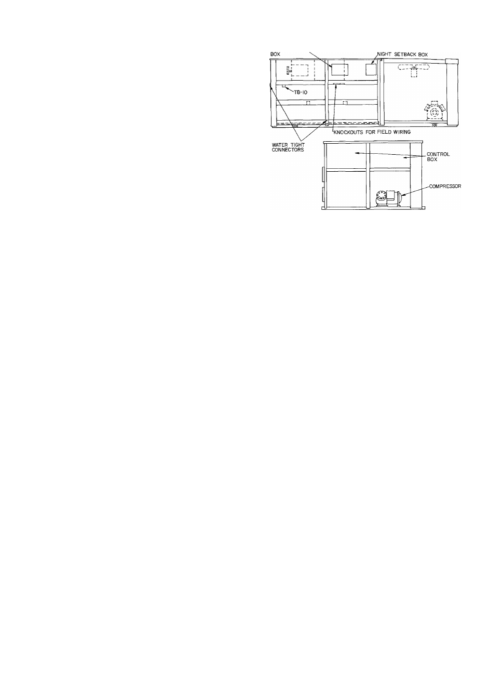
with a remote box and a night setback box. The remote
box contains a 7-day time clock, a bypass switch that can
manually bypass the time clock for up to 5 hours, 6 indi
cator lights and 2 terminal blocks for field wiring con
nections. Mount this box remote from the unit in an
indoor or weathertight space. The night setback box
contains a terminal block for field wiring conneetions, a
morning warm-up thermostat and the setback/setup
module. The night setback box remains in the unit. Ship
ping locations of remote box and permanent location
of night setback box are shown in Fig. 12.
1. Remove remote box and mount in a restricted access
area (indoors or in a weathertight space).
2. Run separate 115-volt, 60-Hz (230-volt, 50-Hz) power
to the remote box per Fig. 11. Use no. 14 AWG wire
or larger and a proper field-supplied electrical
connector.
3. Install a Carrier-approved accessory electronic
thermostat or transmitter if remote sensor is used
(subbase not required) according to the installation
instructions included with the accessory. Note that
the subbase is not used on units with the energy
management accessory. Locate the thermostat or
rernote sensor, if used, in the conditioned space where
it will sense average temperature.
Route thermostat cable or equivalent single leads of
no. 18 AWG colored wire from thermostat or trans
mitter terminals through connector on unit to low-
voltage (TB4) connections in main control box as
shown on unit label wiring diagram and in Fig. 11.
4. Run 24-volt wires between the remote box and night
setback box per Fig. 11. Use no 18 AWG wire for
lengths up to 1000 feet. Local codes may dictate use
of conduit for low voltage. Knockouts are provided in
the night setback box and in the fan deck separating
heating section from section containing the night
setback box (Fig. 12). A watertight connector is in
stalled in side of unit. Two rubber grommets are taped
inside the night setback box. Use grommets in knock
outs in fan deck and night setback box.
REMOTE CONTROL
Fig. 12 — Shipping Locations — Remote Box
Return Air Filters — Check that return air filters are
of the correct type and size and installed in unit filter
racks. Filter data is shown in Table 1 Do not operate
unit without return air filters
Outdoor Air Inlet Screens — Outdoor air inlet
screens must be in place before operating unit.
Compressor(s) — Loosen compressor holddown
bolts until sidewise movement of the washer under each
holddown bolt head occurs Do not loosen completely
as bolts are self-locking and will maintain their
adjustment.
Open the compressor discharge and suction service
valves. Replace and tighten valve caps to prevent leaks.
Liquid Line Service Valve — Open the liquid line
service valve Replace and tighten valve cap to prevent
leaks.
Low Ambient Compressor Lockout(Fig. 13) —
All units are equipped with an adjustable low ambient
lockout thermostat to lock off the compressor(s) at low
outdoor air ambients. Thermostat is located in the main
control box. Setting will depend on specific installation
but should be approximately 55 F on constant volume
units.
Convenience Outlet — All units are equipped with
a 115-volt convenience outlet for handling small power
load or service light. See Fig. 13.