Carrier 50DF034 User Manual
Installation, start-up and service instructions
Attention! The text in this document has been recognized automatically. To view the original document, you can use the "Original mode".
HEATING & COOLING
50DF034
Single-Package Cooling Units
Installation, Start-Up and
Service Instructions
SAFETY CONSIDERATIONS
Installation and servicing of air conditioning
equipment can be hazardous due to system pressure and
electrical components. Only trained and qualified service
personnel should install, repair or service air conditioning
equipment.
Untrained personnel can perform basic maintenance
functions of cleaning coils and filters and replacing filters.
All other operations should be performed by trained
service personnel. When working on air conditioning
equipment, observe precautions in the literature, tags and
labels attached to the unit and other safety precautions
that may apply.
Follow all safety codes. Wear safety glasses and work
gloves. Use quenching cloth for unbrazing operations.
Have fire extinguisher available for all brazing
operations.
A
WARNING
Before performing service or maintenance operations
on unit, turn off main power switch to unit. Elec
trical shock could cause personal injury.
INSTALLATION
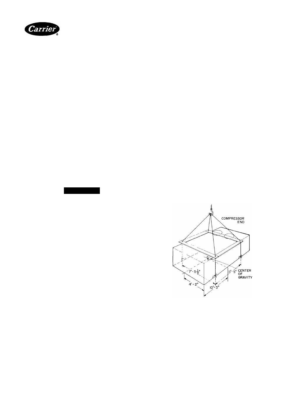
Rigging and Unit Placement — Inspect unit for
transportation damage. File claim with transportation
agency. Do not remove shipping skid until unit is ready
to be set in final location. Do not drop unit; keep upright.
Use spreader bars over unit to prevent sling or cable
damage. Rollers may be used to move unit across a roof.
Level by using unit frame as reference. See Fig. 1 for
additional information. Unit weight is shown in Table 1.
Units are designed to be hoisted only. However, units
with optional shipping skids may be moved with a fork
truck. Refer to Accessory Roof Curb Installation Instruc
tions for additional information as required.
Roof Curb — Assemble and install as described in
instructions shipped with this accessory. Accessory roof
curb and information required to field fabricate a roof
curb of 2-in.
X
14-in. planks is shown in Fig. 2. Install
insulation, cant strips, roofing and flashing as required.
For unit drains to function properly, curb must be level
or within tolerances shown in Fig. 3.
Roof Mount — Check building codes for weight dis
tribution requirements Unit weight is shown in Table 1.
Slab Mount — Provide a level concrete slab that
extends beyond unit cabinet at least 6 inches. Make a slab
8 in. thick with 4 in. above grade. Use gravel apron in
front of condenser air inlet to prevent grass and foliage
from obstructing airflow.
Alternate Unit Support Methods — Where the
preferred curb or slab mount cannot be used, support
unit with sleepers on perimeter, using curb support area.
However, if sleepers cannot be used, support long sides
of unit (dimension A, Fig. 4) with three 4-in. x 4-in. pads
equally spaced. U nit may sag if supported by corners only.
Positioning — Unit condenser air inlets and outlets
may be located in any compass direction since they are
not affected by wind. Provide clearances around and
above unit for airflow, safety and service access (Fig 4).
Do not install unit in an indoor location Do not locate
air inlets near exhaust vents or other sources of con
taminated air
Although unit is weatherproof, guard against water
from higher level runoff and overhangs.
NOTES-
1 All unit panels must be In place when rigging.
2 Do not handle unit with fork trucks
3 Use 4 cables and four 2-by-4’s or 4-by-4's of dimensions
shown.
Fig. 1 — Rigging Details
Manufacturer reserves the right to discontinue, or change at any time, specifications or designs without notice and without incurring obiigations.
Book|l
PC111
Catalog No 565-032
PrintedinUSA
Form 50DF-9SI
Pgl
4-86
Replaces: 50DF-7SI
For replacement items use Carrier Specified Parts
Tab lib