Service, Electronic component checkout, A caution – Carrier 50DF034 User Manual
Page 13
Attention! The text in this document has been recognized automatically. To view the original document, you can use the "Original mode".
3. Remove spring on motor shaft.
4. Adjust switch as shown in Fig. 17.
5. After adjustment, replace spring on motor shaft and
reassemble return spring housing.
CAPACITY CONTROL, HEATING — Stages 1 and 2
of heaters are controlled by heating relays H R1 and H R2,
respectively. Using a suitable ammeter, check heater
current draw for heating assemblies or elements. When
checking second-stage heater operation, be sure heating
thermostat is set high enough to activate second-stage
heaters Also, check operation of outdoor air thermo
stats if additional staging is provided
TIME GUARD® CIRCUIT — Timer sequence for a
particular unit depends on unit and compressor arrange
ment. The Time Guard device provides a delay in com
pressor start-up after thermostat closes. On normal unit
start-up, outdoor air fans energize 15 seconds before the
compressor. If compressor/shutdown is due to satisfied
thermostat or automatic resetting of a safety device, the
compressor automatically restarts after a 5-minute
interval. If compressor shutdown is due to tripped over
loads, the circuit breakers must be manually reset before
compressor will start.
Timer (Time Guard) for second compressor has a 6-
minute interval to prevent compressors from starting
simultaneously.
Refer to unit label diagram for specific timer sequence.
CRANKCASE HEATER — Unit main power supply
must remain on to provide crankcase heater operation.
Crankcase heater in each compressor keeps oil free of
refrigerant while compressor is off.
HEAD PRESSURE CONTROL — Each unit has a fan
cycling thermostat to shut off outdoor fan motors at 55 F.
This permits unit to operate with correct condensing
temperatures down to 35 F outdoor air temperature.
SERVICE
Electronic Component Checkout
A CAUTION
Control circuit must be checked with system power
on. Disconnect power before checking wiring and use
care to avoid electrical shock and prevent equipment
damage.
____________________
The checkout procedures in this section will determine
whether-
1. The logic panel is controlling the heating and cooling
equipment properly.
2. System components are correctly wired to the logic
panel.
Prior to checking out control circuit, establish setting
on the low ambient lockout thermostat. Compressors
will not start below this setting (cooling mode only).
Recommended setting is approximately 50-55 F.
NOTE: To complete the electronic component checkout,
a volt-ohmmeter (Simpson 260 is recommended) is
required.
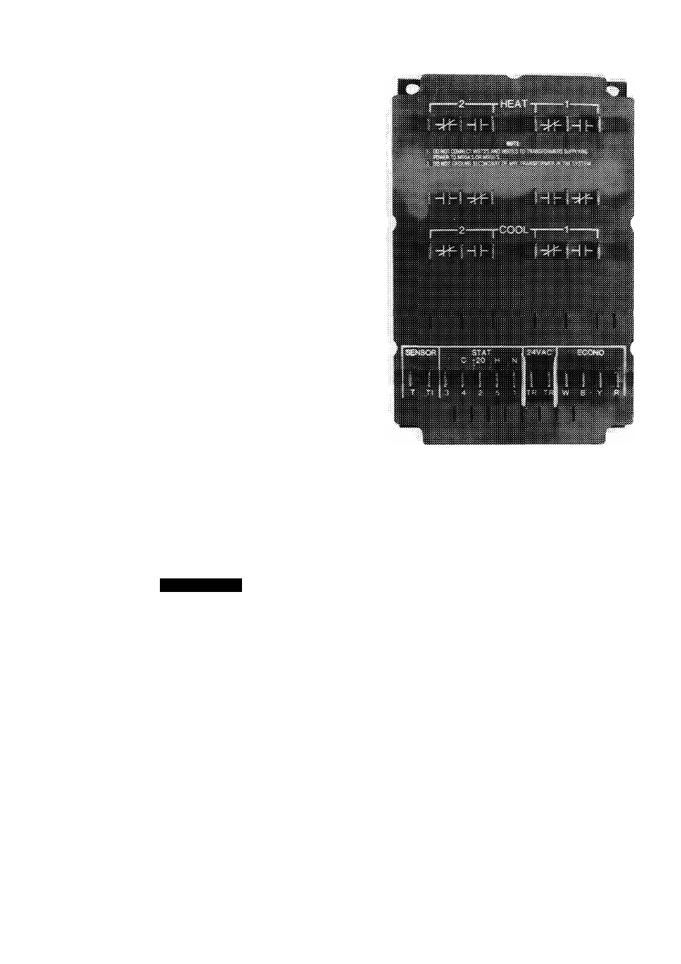
LOGIC PANEL (Fig. 18)
I. Check that 24 vac is supplied to logic panel Connect
meter to terminals TR.
2 Check thermostat supply voltage at STAT terminals
1 and 2. Reading should be 20 vdc.
Fig. 18 — Logic Panel (Standard Unit)
3 Remove thermostat supply wires from ST AT ter
minals 1 through 5 on logic panel.
4. Set meter to volts ac scale equal to relay switching
voltage (50-volt scale for 24 vac).
5. To simulate a call for cooling, jumper between STAT
terminals 2 and 4. Normally open logic panel contacts
(COOL 1 and 2) should close and cooling equipment
should cycle on.
6. Connect meter leads to the normally open cooling
contacts 1 and 2 on logic panel. Meter should read zero
if contacts have closed and contacts are made.
If meter is reading zero and cooling equipment has
not cycled on, logic panel is not at fault.
7. To simulate a call for heating, jumper between ST AT
terminals 2 and 5. Normally open logic panel contacts
(HEAT 1 and 2) should close and heating equipment
should cycle on.
8. Connect meter leads to the normally open heating
contacts on logic panel. Meter should read zero if
contacts have closed.
If meter is reading zero and heating equipment has
not cycled on, logic panel is not at fault.
9. Replace thermostat wiring to terminals 1 through 5.
DISCHARGE SENSOR
1 Set resistance on meter to R x 100.
2. Disconnect lead from SENSOR terminal T1 on logic
panel.
13