Economizer section, A caution – Carrier 50DF034 User Manual
Page 3
Attention! The text in this document has been recognized automatically. To view the original document, you can use the "Original mode".
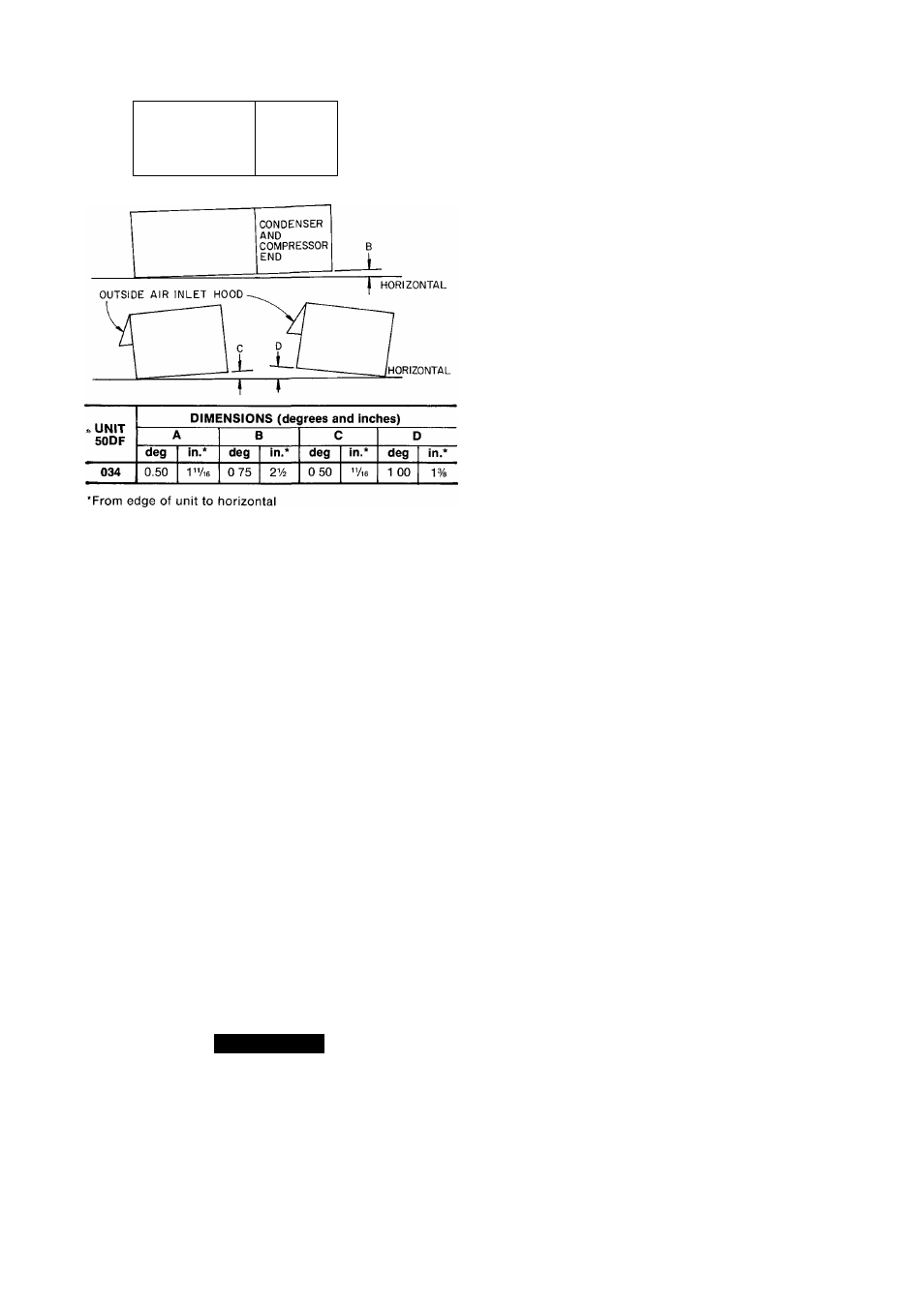
CONDENSER
AND
COMPRESSOR
END
HORIZONTAL
Fig. 3 — Unit Leveling Tolerances
Economizer Section
ECONOMIZER HOOD INSTALLATION (Fig. 7) —
The economizer mechanism and all electrical connections
are factory installed and adjusted except as noted below.
Hood assembly, outdoor air inlet screens and required
hardware are shipped separately and must be field
installed.
Install economizer hood and enthalpy control as
follows:
1. Loosen unit top panel sheet metal screws above out
door air inlet opening.
2. Assemble hood top panel, side panels and support
channel.
3. Insert hood flange between unit top panel flange and
unit. Slots are provided in hood flange to clear sheet
metal screws. Tighten sheet metal screws. To insure
water tightness, apply RTV to edges as indicated
by shaded portions of Fig. 7.
4. Secure hood side panels to outdoor air opening
flanges, using screws provided.
5. Install hood support bracket(s) between U-channel
and support channel.
6. Install screen retainer on support channel, using
screws in the slots. Do not tighten.
7.
A CAUTION
Shut off main power to unit before installing
enthalpy control assembly.
8. Remove enthalpy control assembly from shipping
location on horizontal deck in return air filter
compartment.
9. Using 4 no. 10-1/2 screws from envelope in control
assembly junction box, mount enthalpy control
assembly to inside of economizer hood side panel
nearest condenser section (Fig. 4).
10. Route the red and yellow wires through knockout
in side plate. Wrap end of blue wire with electrical
tape. Using wire connectors from envelope injunc
tion box, wire enthalpy control assembly as shown in
Fig. 8. Use strain reliefs from envelope on side plate
and junction box. Refer to Fig. 9 for Psychrometric
Chart for enthalpy control.
11. Install outdoor air screens.
12. Push retainer snugly against screens and tighten
screws.
Exhaust Air Hood Installation — The optional
power exhaust hood and damper assemblies and required
sheet metal screws are shipped in the compartment at
right of indoor air fan motor compartment. Using screws
provided, install a hood damper assembly over each
exhaust air opening as shown in Fig. 4. Power exhaust is
applied only to economizer units using bottom duct con
nections. Exhaust fan and motor assembly is factory
wired and adjusted. Refer to Service, Power Exhaust Air
Fan Adjustment if required.
Indoor Air Fans — The fan belt and pulleys are factory
installed and adjusted. If required, adjust as described
in Service, Indoor Air Fan Adjustment.
Condensate Drains — See Fig. 4 for drain locations.
Condensate drain is open to atmosphere and must be
trapped. Install a trapped drain line at connection to be
used. Trap must be at least 3 in. deep and made of flexible
material or be installed to prevent freeze-up.
Condensate drain pan under unit is fitted with a one-in.
FPT coupling. A gasket is shipped taped to this drain.
Install gasket in unit basepan opening or alternate open
ing on end of unit.
Field Power Supply — Unit is factory wired for
voltage shown on nameplate. The main power terminal
block is suitable for use with aluminum or copper wire.
See Fig. 10 and 11. Units have circuit breakers for
compressors, fan motors and control circuit. If required
by local codes, provide an additional disconnect switch.
If an external electrical source is used, unit must be
electrically grounded in accordanee with local codes, or
in the absence of local codes, with the National Electrical
Code, NFPA 70.
All field wiring must comply with National Electrical
Code and local requirements.
Install conduit connector in unit basepan or side panel
openings provided as shown in Fig. 4. Route power lines
through connector to terminal connections in control box
as shown in Fig. 10 and 11.
Affix crankcase heater sticker to unit disconnect
switch.
Voltage to compressor terminals during compressor
operation must be within voltage range indicated on unit
nameplate. Also, see Table 2. Phases must be balanced
within 2% Contact local power company for correction
of improper voltage or phase unbalance. Failure due to
operation of unit on improper line voltage or with exces
sive phase unbalance constitutes abuse and may cause
damage to unit electrical components.