Carrier 38GP User Manual
Page 4
Attention! The text in this document has been recognized automatically. To view the original document, you can use the "Original mode".
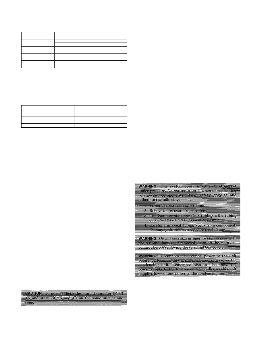
TABLE Vili—RECOMMENDED
SUCTION-TUBE DIAMETERS
Size
Suction-Tube
Length (Feet)
Recommended
Diameter (inches)
025
0 to 120
5/8
120 to 150
7/8
040
Oto 60
3/4
60 to 135
7/8
047
Oto 85
7/8
85 to 150
1-1/8
054
0 to 65
1-1/8
65 to 150
1-3/8
NOTE: The above table is based on a tube loss of 2°F. Longer lengths
can be used in each diameter listed, or smaller diameters may
be used, but the result will be larger tube losses with a lower
unit capacity and efficiency rating. Refer to your Distributor for
specific details.
TABLE IX—REQUIRED PISTON SIZE FOR
INDOOR COIL
Condensing
Unit Size
Piston
identification No.
025
59
040
76
047
82
054
88
NOTE: The piston sizes listed in this table are for systems where the
vertical separations between indoor and outdoor units do not
exceed 10 feet. For vertical separations exceeding 10 feet,
consult the factory for the proper piston sizes.
If other than matching interconnecting tubing or evapora
tor coU is being used, use an accurate scale or volumetric
charging cylinder (such as a Dial-A-Charge) and weigh in the
refrigerant until the desired superheat temperature is
obtained. See the superheat charging label attached to each
condensing unit.
When system charging has been completed, stamp the total
amount of refrigerant in the block provided on the condens
ing unit rating plate. The total system charge is the same as
the field charge.
C. Determining Suction-Tube Diameter
The correct suction-tube diameter can be determined by
using Table VIII as follows:
1. Measure total length (vertical and horizontal) of
intended tubing path.
2. Find correct unit size at left of table.
The tube lengths are shown in the center of the table
with the appropriate diameters on the right.
iX. SEQUENCE OF OPERATiON
When the thermostat “calls for cooling,” the thermostat
contacts close, energizing contactor holding coil 2D or 2M
from a 24-volt external power source. The contactor closes,
energizing compressor motor 3F or 3J and condenser fan
motor 3C or 3D with supply voltage.
When the thermostat is satisfied, the contacts open,
deenergizing contactor holding coil 2D or 2M and, in turn,
breaking the supply voltage circuit. AH motors should stop.
Optional Start Assist (When Used)
Start thermistor 4K is wired in parallel to run capacitor 4G
on single-phase units. Its purpose is to provide additional
start assist. When compressor 3J starts, start thermistor
4K builds its internal resistance to a level where it effec
tively removes itself electrically from circuit. When contac
tor 2D or 2M is deenergized, start thermistor 4K will auto
matically reset itself in approximately 3 to 5 minutes.
Start Kit 2K and 4D
The start kit consists of start relay 2K and start capacitor
4D. Start capacitor 4D helps compressor 3J start. When the
compressor starts, start relay 2K disconnects start capaci
tor 4D from the circuit, allowing compressor 3J to run on
run capacitor 4A or 4G. When contactor 2D or 2M deener
gizes, start relay 2K reconnects the start capacitor in the
circuit, making it ready for the next compressor start.
X. CARE AND MAINTENANCE
For continuing high performance, and to rnmirnize possible
equipment failure, it is essential that periodic maintenance
be performed on this equipment. Consult your local Dealer
for the proper frequency or maintenance and the availability
of a maintenance contract.
The air for the condenser coil is drawn into the unit on four
sides and discharged out the top. Keep the air inlet and out
let grilles unplugged and clear of any obstructions at all
times. Never cover the unit or lean anything against it
which might restrict airflow or cause hot air from the top
grille to recirculate into the sides. Keep trash and debris
away from the uiut at all times. Never stand on the unit or
use it as a support for ladders, etc.
The refrigerant tubing connecting this unit with the coohng
coil is easily crushed or crimped. Therefore, do not hang or
stand anything on it. Do not move the unit after it has been
installed, as this may crimp the tubing and cause the unit to
malfunction.
The ability to properly perform maintenance on this equip
ment requires certain mechanical skills and tools. If you do
not
possess
these,
contact
your
Distributor
for
maintenance.
The minimum maintenance that should be performed on
this equipment is as follows:
1. Check condenser coü for cleanliness each month during
cooling season. Clean as necessary, but at least once at
the beginning of each cooling season. To insure reliable
performance in sea coast or contaminated atmosphere
installations, the unit must be kept free of debris and
the condenser coil flushed with fresh water at least
once a month. See Section X, item A, for proper
procedures.
—4—