Table iv—unit size 025, Table v—unit size 040, Table vi—unit size 047 – Carrier 38GP User Manual
Page 3: Table vii—unit size 054
Attention! The text in this document has been recognized automatically. To view the original document, you can use the "Original mode".
All of the above steps are covered in general by the like-
numbered sections of the Standard Installation Practices in
the back of this manual; therefore, this Installation Instruc
tion will contain only supplementary information applicable
to installing the condensing unit. It should be noted that
evacuation and purging are not normally required when a
complete matching system is installed. However, if any of
the component parts are subject to contamination, or if tub
ing kits and matching coUs are not used, the system must
be purged or evacuated.
NOTE;
Be sure to adjust system airflow per requirements of
the
fan-coil,
evaporator
coil,
and
condensing
unit
combination.
In addition, the following sections should be reviewed by
the equipment owner;
IX. Sequence of Operation
X. Care and Maintenance
I. LOCATING THE UNIT
(Supplementary Instructions)
Select a location for the unit where water, ice, emd snow will
not fall from an overhang and damage the unit top or fan
blade. Care must be exercised to maintain the clearance
requirements listed on page 2 to assure proper access for
servicing and to avoid recirculation of condenser air.
II. INSTALLING REFRIGERANT TUBES
(Supplementary Instructions)
A. Determining Liquid-Tube Diameter
The correct liquid-tube diameter cem be determined by using
the appropriate table as described in steps 1 through 7
which follow. Be certain to use only the hquid-tube table
that matches the size unit being installed. (See Tables IV
thru VII.)
1. Measure total one-way horizontal distance for intended
tubing path.
2. Measure total one-way vertical distance for intended
tubing path.
3. At left-hand end of table, select value that matches
measured vertical length. Be sure to note that upper
section of table is used if coohng coü is above unit,
whereas lower section is used if cooUng coil is below
unit.
4. Move across this Une towards right-hand side until cor
rect vertical column is reached for measured horizontal
length.
5. Correct diameter will be indicated at intersection of
these lines.
6. If point of intersection falls within shaded area, crank
case heater must be added.
7. For apphcations where coohng coil is to be placed more
than 50 feet below unit, see your Distributor for spe
cific recommendations.
Here is an example; Unit is size 025. Coohng coil is located
43 feet above unit. Horizontal distance is 72 feet.
First, in the section marked “Coü Above Unit,” find the hne
showing measurement of 41-50 feet. Follow this line
towards the right until it intersects the vertical colunrn
marked 71-80 feet. The correct tube size is 5/16-inch OD,
and the fact that the 5/16-inch size falls in the shaded area
means that the unit wih require a crankcase heater.
B. Instructions for Total System Charge
The total system refrigerant charge includes the condensing
unit, the evaporator coü, and the interconnecting tubing.
The factory charge is sufficient for a system using 25 feet of
interconnecting tubing and a matching evaporator coil. For
systems using tubing lengths other than 25 feet, adjust the
charge in accordance with the notes under the proper table
(IV through VII).
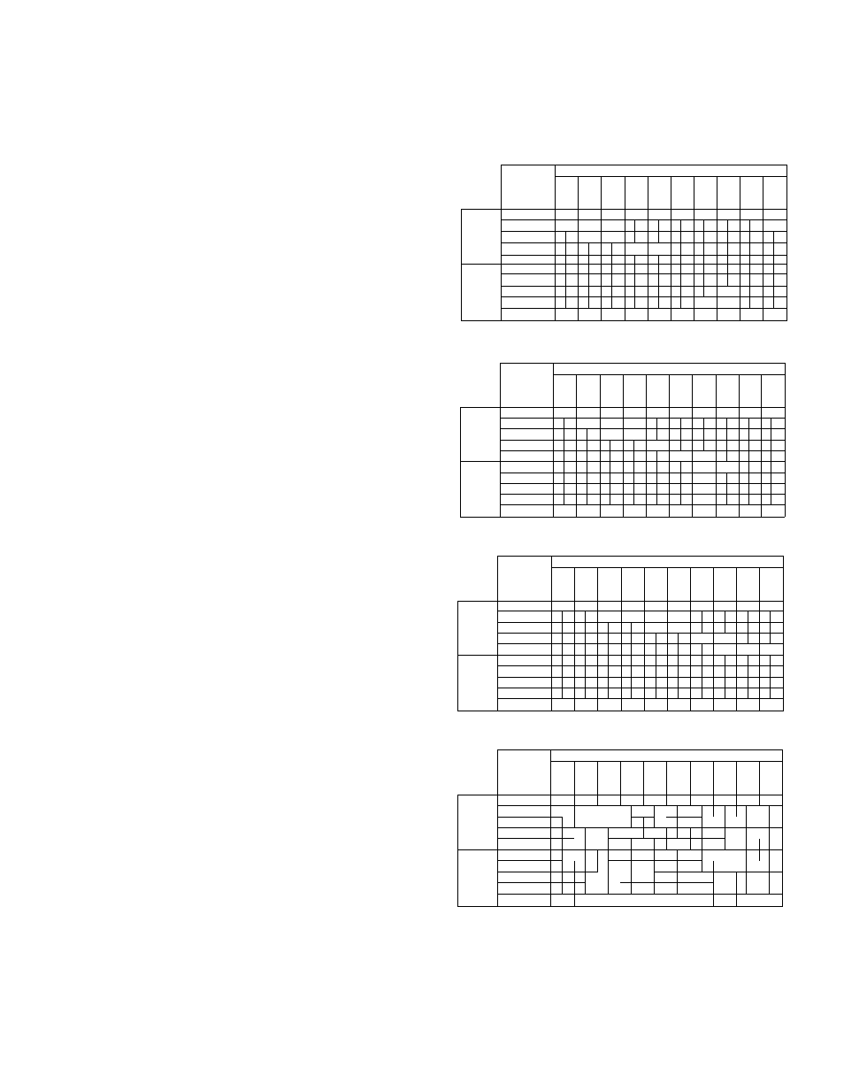
TABLE IV—UNIT SIZE 025
Horizontal Distance- -Feet
Vertical
D
11
21
31
41
51
61
71
81
91
Distance
to
to
to
to
to
to
to
to
to
to
(Ft)
10
20
30
40
50
60
70
80
90
100
41 to 50
5/16 5/16 5/46 5/16 5/16 5/-16 5/16 5/16 5/16
3/8
Coil
31 to 40,
1/4
t
t
5/16
Above
21 to 30
1/4
1/4
Unit
11 to 20
1/4
1
Oto 10
Oto 10
Coil
11 to 20
Below
21 to 30
1/4
Unit
31 to 40
1/4
1
41 to 50
1/4
1/4
51«; /3«,
4,/4,<
5/16 5/16 5/J6 5/16
TABLE V—UNIT SIZE 040
Horizontal Distance— Feet
Vertical
a
11
21
31
41
51
61
71
81
91
Distance
to
to
to
to
to
to
to
to
to
to
(Ft)
10
20
30
40
50
60
70
80
90
100
41 to 50
1/4
5/16 5/16 5/16 5/16 5/16 5,'16 5/16 5/16 5/16
Coil
31 to 40
1/4
t
t
Above
21 to 30
1./4
1/4
Unit
11 to 20
1/4
Oto 10
1/4
Oto 10
1/4
Coil
11 to 20
Î
Below
21 to 30
1/4
Unit
31 to 40
41 to 50
1/4
1/4
1/4
1/4
1/4
1,-4 5/16 5/16 5./16 5/16
TABLE VI—UNIT SIZE 047
Horizontal Distance— Feet
Vertical
11
21
31
41
51
61
71
81
91
Distance
to
to
to
to
to
to
to
to
to
to
(Ft)
10
20
30
40
50
60
70
80
90
100
41 to 50
5/16 5/16
3/8
3/8
m/§
3/8
3/8
3/8
3/8
Coil
31 to 40
5/16 5/16
.t
Above
21 to 30
5/16 5/16
Unit
11 to 20
5/16 5/16
Oto 10
t
5/16 5/16
Oto 10
Coil
11 to 20
Below
21 to 30
Unit
31 to 40
41 to 50
5/16 5/16 5/16 5/16 5/16 5/16 5/16 5/16 5/16 5/16
TABLE VII—UNIT SIZE 054
Horizontal Distance— Feet
Vertical
11
21
31
41
51
61
71
81
91
Distance
to
to
to
to
to
to
to
to
to
to
(Ft)
10
20
30
40
50
60
70
80
90
100
41 to 50
3/8
3/8
3/8
3/8
3 5
3./8
3/8
3/8
3,'8
3/8
Coil
31 to 40
5/ 16
t
Above
21 to 30
5.'16] 5/ 1 6
Unit
11 to 20
5/
5.'16
Oto 10
' ’
1
'
5/16
Oto 10
i J
5 1 6
Coil
11 to 20
1
i
Below
21 to 30
6
Unit
31 to 40
4
. . .
41 to 50
5/16 5/16|5/16|5/16|5/16|5/16
3/8
3/8
3/8
3/8
(1) Unit charge adequate for 3/8-in. OD tube lengths up to 25 ft. For lengths
below or above 25 ft, adjust charge at rate of 0.6 oz/ft. This may be done by
using superheat charging label.
(2) Unit charge adequate for 1/4-in. OD tube lengths up to 75 ft. For lengths
above 75 ft, adjust charge at rate of 0.2 oz/ft.
(3) Unit charge adequate for 5/16-in. OD tube lengths up to 40 ft. For lengths
above 40 ft, adjust charge at rate of 0.4 oz/ft.
(4) If tube size falls within shaded area, add crankcase heater.
—3—