Carrier 38EC User Manual
Page 9
Attention! The text in this document has been recognized automatically. To view the original document, you can use the "Original mode".
6.
Using a midget tubing cutter, cut liquid and
discharge lines on the coil and suction line at a
convenient place for easy reassembly with
copper slip couplings.
8
.
After plugging connections, remove condenser
coil by pinching plastic pins of tube supports
that extend into basepan and lift vertically. Set
coil on a clean, flat surface.
Remove compressor holddown bolts and slide
out compressor. Remove crankcase heater, if
so equipped.
9. Carefully unbraze suction and discharge line
piping stubs from compressor after noting posi
tion of stubs to assist when reinstalling.
10.
Install new compressor, placing crankcase
heater around compressor, if so equipped. Be
sure compressor holddown bolts are in place.
11. Replace coil; braze suction and discharge lines
to compressor piping stubs (at points where eut.
Step 6); rewire compressor and leak test.
12. Replace fan orifice/control ring; connect com
pressor wires after feeding them thru eontrol
ring; replace fan/grille assembly and rewire;
connect high- and low-voltage power wiring;
and replace louvered casing.
13. Replace top cover by running screws into orifice
loosely and tighten when cover is in plaee.
14. Evacuate and reeharge system.
Filter Drier
— Install field-supplied filter drier
(Table 3) in system liquid line when refrigerant
system is opened for serviee as described under
Compressor Removal. Position drier in liquid line
at convenient loeation.
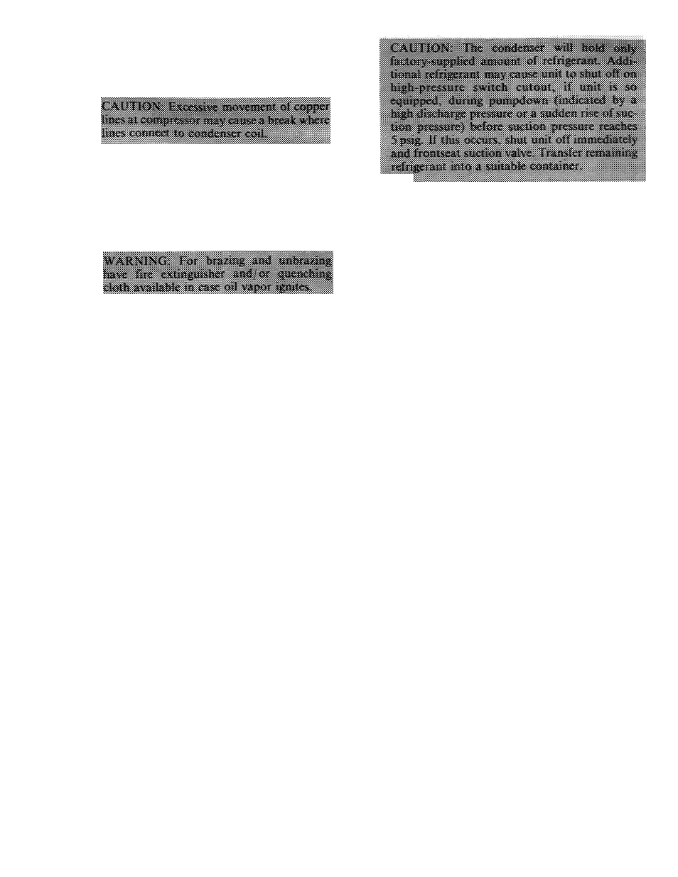
Pumpdown Procedure
— The system may be
pumped down in order to make repairs on low side
without losing eomplete refrigerant charge.
1. Attach pressure gage to suction service valve gage
port.
2. Frontseat the liquid line service valve.
3. Start unit and run until suction pressure reaches
5 psig (see Caution).
4. Shut unit off and frontseat suction valve.
5. Vent remaining pressure to atmosphere.
1
Unit Controls and Safety Devices
HIGH-PRESSURE RELIEF VALVE is located in
eompressor. Relief valve opens if system operating
pressure differential between suction and discharge
pressure reaches 400 to 500 psi on all models.
LOW-PRESSURE SWITCH is located on unit
suction line. Low-pressure switch settings are: cut
out, 31 ± 4 psig; cut-in, 60 (+15, -0) psig.
INTERNAL
TEMPERATURE
AND/OR
CUR
RENT SENSITIVE OVERLOADS reset automati
cally when motor internal temperatures drop to a
safe level (overload may require up to 30 minutes to
reset). When internal overload is suspected of being
open, check by using an ohmmeter or continuity
tester. If neeessary, refer to Carrier Standard Serv
ice Techniques Manual, Chapter 2, Eleetrical, for
complete instructions.
INHERENT FAN MOTOR PROTECTION pro
tects motor from abnormal current and temperature.
FAN SWITCH changes to high speed at 90 F ± 5;
changes to low speed at 75 F ± 5.
SOLID-STATE
TIME
GUARD
II
CIRCUIT,
if so equipped, protects unit compressor by prevent
ing short cycling. Time Guard II circuit provides a
5 ± 2-minute delay before restarting compressor
after shutdown for any reason. On normal start-up,
the 5-minute delay occurs before thermostat closes.
After thermostat closes, the Time Guard 11 circuit
then provides a 3-second delay to prevent contactor
chattering.
CRANKCASE
HEATER
keeps
the
crankcase
warm during the off cycle and thus prevents dilution
of the oil with refrigerant. This assures good lubriea-
tion and prevents loss of oil from crankcase during
start-up.
CRANKCASE HEATER SWITCH (relay for 060,
3-ph, 460-v units only) deaetivates heater when
compressor is operating for maximum energy
efficiency.
START
CAPACITOR
AND
RELAY
assure
proper
compressor
start-up
under
adverse
conditions.