Start-up, Refrigerant charging – Carrier 38EC User Manual
Page 6
Attention! The text in this document has been recognized automatically. To view the original document, you can use the "Original mode".
START-UP
1. Backseat (open) liquid and suction line service
valves. Open liquid line first to equalize pres
sure and reduce oil flow to suction line.
2. Set thermostat selector switch at OFF.
3.
Set room thermostat at desired temperature.
Be sure this temperature is below indoor ambient.
4.
Close electrical disconnects energizing entire
system.
5. Set room thermostat at COOL and fan switch at
FAN or AUTO, as desired. Operate unit for 15
minutes; then check system refrigerant charge.
See Refrigerant Charging, discussed later.
Motors and controls are designed to operate satis
factorily in the voltage range shown in Table 4. If
necessary to use manifold gages for servicing, refer
to Carrier Standard Service Techniques Manual,
Chapter 1, Refrigerants, page 1-5, Fig. 8 for bypass
method of returning charge to system. Removal of
liquid line charging hose without following these
precautions could result in some loss of charge.
Refrigerant Charging
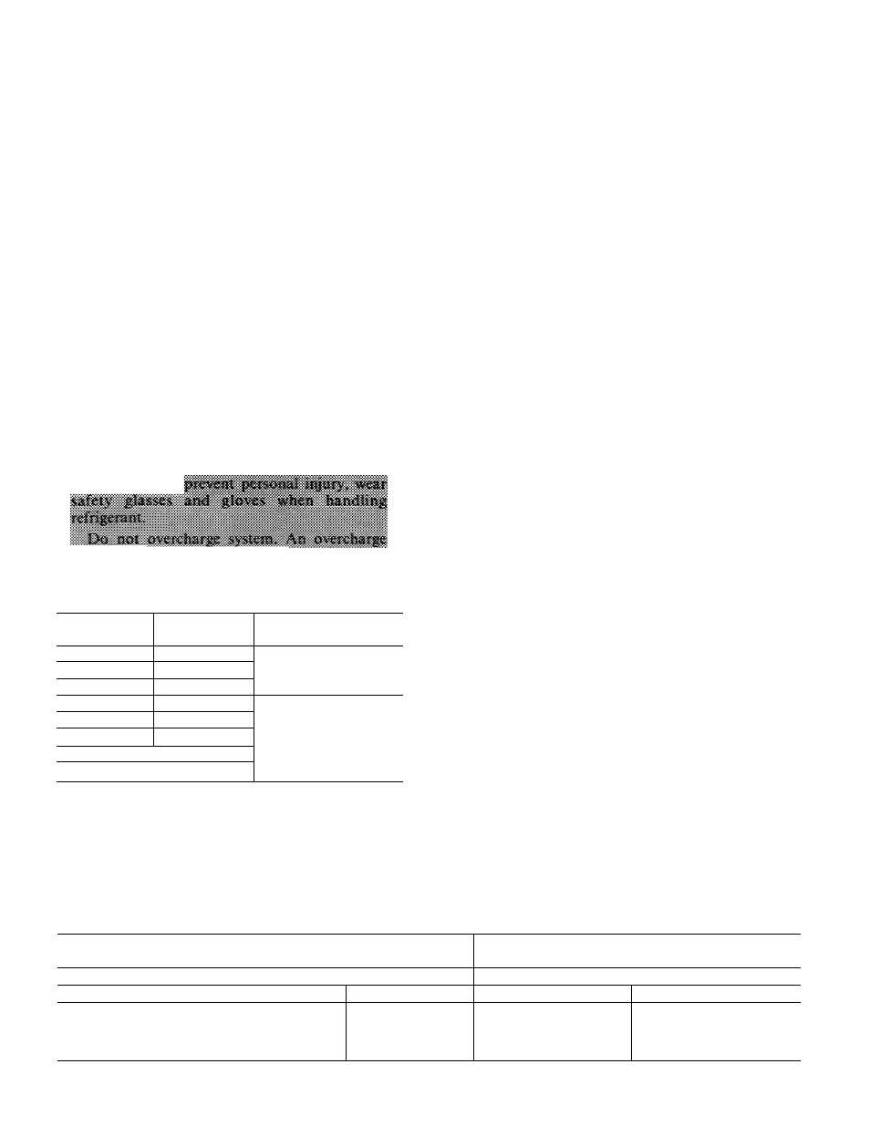
ca» саяш
flooding.
Table 5 — Service Data
UNIT
38EC
R-22 CHG*
(lb)
CONDENSER
FAN RPM (Hi/Lo)
018
3 3
024
3 3
1110/950
030
5 3
036
7.5
042
63
048300
6 1
1075/950
048310
72
060
9 6
‘Factory refrigerant charge is adequate when evaporator and con
densing unit are the same size and are connected with 25 ft or less
of field-supplied tubing of recommended size or Carrier accessory
tubing
Condensing
units
contain
correct
operating
charge for complete system when connected to
Carrier-approved evaporators of same capacity as
condensing unit with 25 ft or less of Carrier accessory
tubing or field-supplied tubing of recommended
size. For every 10 ft of liquid line of recommended
size over 25 ft, add refrigerant charge as follows: .41b
for 3/8-in. line; .28 lb for 5/ 16-in. line. On all other
systems, adjust eharge for correct operation as
applicable.
Service port eonnections are provided on liquid
and suction line service valves for evacuation and
charging. See Fig. 1.
TO CHECK, ADJUST OR REPLACE REFRIG
ERANT CHARGE use method recommended in
Table 6. Details of charging methods are listed
below.
Before recharging system, thoroughly evacuate
system and then weigh in refrigerant charge speci
fied in Table 5. Check or adjust charge as required.
Refer to Carrier Standard Service Techniques
Manual, Chapter 1, Refrigerants, for additional sys
tem evacuation and dehydration instructions.
WEIGHT METHOD — Refer to Table 5 or unit
nameplate for correct system refrigerant charge.
Remove any refrigerant remaining in system before
recharging.
When system is not evacuated, subtract the
following amount from total charge.
38EC018 thru 030 — .10 lb (1.6 oz)
38EC036 thru 060 — .20 lb (3.2 oz)
The Dial-a-charge charging cylinder is an accu
rate device used to recharge system by weight. These
cylinders are available at refrigeration supply firms.
CHARGING CHART METHOD — Use Charging
Chart, Fig. 6, and the following procedure.
1. Operate unit a minimum of 10 minutes before
checking charge.
Measure suction pressure by attaching a gage to
suction valve service port.
Measure suction line temperature by attaching a
service thermometer to unit suction line near suc
tion
valve.
Insulate
bulb,
thermocouple
or
thermistor for accurate reading.
2
.
3.
f:
Table 6 — Refrigerant Charging Methods
I
METHODS OF CHECKING OR
roNniilMlT ADJUSTING CHARGE
METHODS FOR COMPLETE
RECHARGING
38EC
1
System Refrigerant Control
System Refrigerant Control
1
Non TXV
TXV
Non TXV
TXV
1 Chargemaster®
ALL 1 or
1 Charging Chart
Sight
Glass*
Weight Method
plus
Chargemaster or
Charging Chart
Weight Method
plus
Sight Glass*
‘Sight glass field supplied and installed in liquid refrigerant line