Carrier 38EC User Manual
Page 7
Attention! The text in this document has been recognized automatically. To view the original document, you can use the "Original mode".
(AccuRater™ System)
4. Measure outdoor (condenser inlet) air dry-bulb
temperature with a second thermometer.
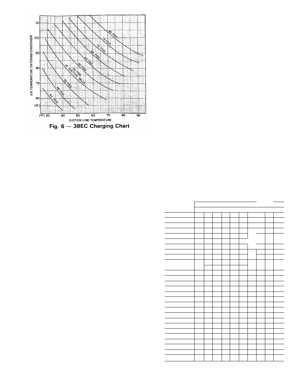
5. Refer to Charging Chart (Fig. 6). Find air tem
perature entering condenser and project hori
zontally to curve showing suction pressure (psig
at suction valve).
6. From this intersection, project vertically down
ward to suction line temperature.
7. If unit has a higher suction line temperature than
charted
temperature,
add
refrigerant
until
charted temperature is reached.
If unit has a lower suction line temperature than
charted temperature, bleed refrigerant until
charted temperature is reached.
If air temperature entering condenser or pressure
at suction valve changes, charge to new suction
line temperature indicated on chart.
8
.
9.
CHARGEMASTER® METHOD — Operate unit
for 10 minutes before using Chargemaster (Carrier
Part No. 38GC680004).
1. Tape Chargemaster feeler bulb to suction line
close to condensing unit. Insulate bulb. Ensure
suction line is clean for good contact with bulb.
(Uninsulated bulb or dirty suction line will seri
ously affect accuracy of temperature readings.)
2. Connect refrigerant drum to Chargemaster inlet
port keeping drum in position for vapor charging.
3. Connect Chargemaster outlet port to unit suction
valve service port.
4. Crack valves on refrigerant drum and Charge-
master to purge lines from drum to suction valve.
After purging lines, close valve on Chargemaster
only.
5. Measure outdoor air dry-bulb temperature.
6. Crack unit suction valve and read evaporator
temperature at red needle position on Charge-
master temperature gage and suction line tem
perature at black needle position.
7. Enter Chargemaster Charging Chart, Table 7, at
outdoor air temperature (step 5) and evaporator
temperature (step 6). Find the suction line tem
perature required for correct system charge. If
actual suction line temperature (step 6) is higher
than table value, the system is undercharged. If
suction line temperature is lower than table
value, system is overcharged.
EXAMPLE: At outdoor air temperature of 84 F
and evaporator temperature of 43 F, the system
will be correctly charged at 76 F ± 2 F suction
line temperature. See Table 7.
Add charge by slowly opening Chargemaster
valve. If necessary, reduce charge by bleeding at
liquid line service valve. Check outdoor air and
evaporator temperature during procedure. If they
change, refer back to Chargemaster Charging
Chart.
Table 7 — 38EC Chargemaster Charging
Chart (AccuRater System)
OUTDOOR
EVAPORATOR TEMPERATURE (F)
TEMP
21
25
28
31
34
37
40
45
48
(F)
Suction Line Temperature (F)
60
32
40
51
62
30
38
39
; ^
64
28
37
47;
60
66
27
35
45 :
57
68
34
43
54
67
70
32
41
52
64
72
31
39
50
61
72
74
30
37
:
48
58
69
76
29
36
46
56
66
78
27
35
44
54
63
75
80
26
33
42
52
61
72
82
32
40
50
59
68
m
3Î
mr im
m
X4£^:«:
86
29
37
46
55
63
73
85
88
35
44
53
61
70
81
90
34
42
51
59
68
78
90
92
33
41
49
57
65
75
86
94
39
47
55
63
72
83
96
38
45
53
61
70
80
98
36
44
51
59
67
77
too
42
49
57
65
75
102
41
48
55
63
73
104
39
46
53
61
70
106
45
51
59
68
108
43
49
57
65
110
41
47
55
63
112
46
53
61
114
50
59
Example