Service, Cailtiomi m iufeisjg or doroags tmy – Carrier 38EC User Manual
Page 8
Attention! The text in this document has been recognized automatically. To view the original document, you can use the "Original mode".
Correct use of Chargemaster ensures that an opti
mum refrigerant charge will be in system when con
ditions
and
system
components
are
normal.
However, the Chargemaster does not solve or fix
system abnormalities. It indicates correct charge for
condition of the system. It will not make corrections
for dirty filters, slow fans, excessively long or short
suction lines or other abnormal conditions. This
charging device ensures that a correct relationship
exists between outdoor temperature, evaporator
temperature, and suction line temperature on a spe
cific system.
SIGHT GLASS METHOD — (Field-supplied sight
glass installed in liquid line.) A satisfactory oper
ating charge can be obtained on thermal expansion
valve systems only by charging to a clear sight glass.
For optimum charge, increase high-side pressure to
380 ± 10 psig by blocking condenser fan discharge
or air entering condenser. Charge to a clear sight
glass while holding constant high-side pressure. For
peak efficiency, adjust charge to yield a liquid refrig
erant temperature at the evaporator that is approxi
mately the same as outdoor dry-bulb temperature.
SERVICE
Compressor Removal
— See Table 8 for com
pressor information and Fig. 7 for component loca
tion. Shut off power to unit. Remove refrigerant
from unit using refrigerant removal methods de
scribed in Carrier Standard Service Techniques
Manual, Chapter 1, Refrigerants. Be sure system
pressure is 0 psig before attempting eompressor
removal.
^
Table 8 — Compressor Data
UNIT
PRODUCTION
OIL CHARGE (oz)t
38EC
COMPR*
Initial
Recharge
018300
AJ8520G
26
24
024300
CRD-0200PFV
55
51
030300
CRF1-0250PFV Ì;
55
51
036300
CRJ1-0300PFV
55
51
042310
AV5542E
54
50
048300
YRD-0400-PFV
72
68
048310
PC5016BD
66
62
060300
PC6416AG
66
62
030500
CRF1-0250-TF5
55
51
036500
CRJ1-0300-TF5
55
51
042510
AV5542E
54
50
048500
YRD6-0400-TFC
72
68
048510
PY5016BD
66
62
060500
PY6416AF
66
62
036600
CRJ1-0300-TFD
55
51
042610
AV5542E
54
50
048600
YRD6-0400-FFD
72
68
048610
PH5016BD
66
62
060600
PH6416AF
66
62
CRANKCASE HEATER SWITCH
SUCTION LINE
LOW
PRESSURE
SWITCH
HOT GAS
DISCHARGE LINE
CONDENSER COIL
COMPRESSOR
DISCHARGE GRILLE (FAN
MOTOR UNDERNEATH) ^
WIRE ACCESS OPENING
TOP COVER-
HIGH-
'/ PRESSURE
SWITCH
FAN MOTOR
AND
COMPRESSOR
LEADS
PLASTIC PIN
OF TUBE
lì SUPPORT
'Refer to Carrier Service Parts Catalog for replacement model
numbers
tWhere piping exceeds 50ft, obtain information from local Carrier
distributor
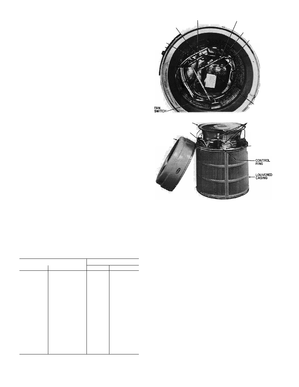
Fig. 7 — Condensing Unit 38EC
Component Locations
Follow safety codes. Wear safety glasses and
work gloves. Have quenching cloth available.
CAilTIOMi
m iufeisjg or doroags tmy
1. Remove top cover: remove 3 screws holding
top cover to connector plate; remove third screw
clockwise from connector plate; loosen remain
ing 5 screws; lift cover straight up.
2. Disconnect high- and low-voltage field wiring
and fan motor leads from capacitor and
contactor.
3. Remove 4 screws (38FC018 thru 030) or 8 screws
(38FC036 thru 060) holding discharge grille in
place. Lift grille from unit.
4. Disconnect compressor leads (crankcase heater,
low-pressure switch, if so equipped) from elec
trical components and pull them thru the wire
access opening into the coil section. Lift fan
orifice/control ring after pinching and pressing
down on 3 plastic pins of tube supports.
5. Remove louvered casing by taking out 16 screws
securing it to the cabinet and sliding it away
from the coil.