Step 3 — make electrical connections — be, See tafek 4 ««t »pply i, Fig. 4 — line power connections – Carrier 38EC User Manual
Page 5: Fig. 5 — control circuit connections
Attention! The text in this document has been recognized automatically. To view the original document, you can use the "Original mode".
Step 3 — Make Electrical Connections
— Be
sure field wiring complies with local and national
fire, safety and electrical codes, and that voltage to
unit is within limits shown in Table 4. Contact local
power company for correction of improper line
voltage.
See Tafek 4
««t »pply i
See Table 4 for recommended wire and fuse sizes.
When making electric connections, provide clear
ance at unit for refrigerant piping connections.
INSTALL A BRANCH CIRCUIT DISCONNECT
PER NEC of adequate size to handle unit starting
current. Locate disconnect within sight from and
readily accessible from the unit, per section 440-14
of National Electrical Code (NEC).
ROUTE LINE POWER LEADS INTO UNIT —
Extend leads from disconnect thru power wiring
hole provided (see Fig. 1) and into unit splice area.
Remove top cover to gain access to unit wiring.
CONNECT
GROUND
LEAD
AND
POWER
WIRING — Connect ground lead to a ground lug
in control box for safety. Then connect power wiring.
See Fig. 4. Splice line power leads to yellow and
black pigtails. Use wire nuts and tape at each con
nection. Connect unit wiring to copper or copper-
clad aluminum power wiring. Do not connect to
aluminum wiring.
CONNECT
CONTROE
POWER
WIRING
—
Route 24-v control wires thru control wiring hole
and connect to pigtails supplied with unit (Fig. 1).
5»^ « £ K
__
o
MWk MW
Mb •! t MV< VWWWM
Eili&SS
tsam UNIT
iifscomiz^
PER
MVWT
-------- ftmwifvni
~ -«ROtiRtS V.E&0 '
UJS
CiMi ìmr
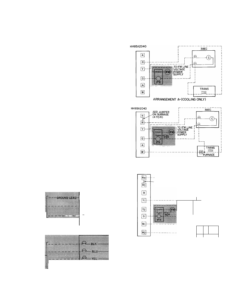
Use furnace or fan coil transformer as 24-v (40-va
minimum) supply for system as shown in Fig. 5, or
use accessory transformer shown in Table 3.
THERMOSTAT
SUBBASE
HH93AZ042 OR
THERMOSTAT
SUBBASE
HH93AZ042 OR
ARRANGEMENT B-ONE TRANSFORMER
(COOLING AND ONE-STAGE HEATING)
THERMOSTAT SUBBASE
HH93AZI76
_LEAVE JUMPER ON
SUBBASE (RH TORO
38EC
____^
1
r _L_
TO IFM LINE
1 1
1 !
VOLTAGE
1
POWER
1
SUPPLY
1
L
-HC2
HC| ITRWS
FURNACE
c
FS
HC
ARRANGEMENT C-ONE TRANSFORMER
(COOLING AND TWO-STAGE HEATING)
IFR, FS and IFM are located in furnace on heating-cooling
applications
If
accessory
IFR
is
required
for
cooling-only
applications, locate IFR in fan coil
— Contactor (12-va)
Trans
— Transformer
— Fan Switch
__
— Heating Control
v-V
Field Splice
IFM
— Indoor Fan Motor
IFR
Indoor Fan Relay
________ Field Wiring
_________ Factory Wiring
Fig. 4 — Line Power Connections
"Connect FS
to low-speed
indoor fan terminal
when 2-speed fan
is used
NOTE Refer to unit wiring label for wire colors C to G and C to Y
connections
^ Fig. 5 — Control Circuit Connections