Start-up – Carrier 380B User Manual
Page 7
Attention! The text in this document has been recognized automatically. To view the original document, you can use the "Original mode".
INSTALL A BRANCH CIRCUIT DISCONNECT
PER NEC of adequate size to handle unit starting
current. Provide a separate disconnect for outdoor
unit, indoor unit and for each accessory electric
' ■ heater circuit as required. (See Indoor Unit and
Electric Heater Installation, Start-Up and Service
Instructions.) Locate disconnect(s) within sight of
and readily accessible from the unit; per section
440-14 of National Electrical Code (NEC).
ROUTE LINE POWER LEADS INTO UNIT ~
Extend leads from disconnect thru power wiring
hole provided (see Fig. 1) and into unit splice area.
Remove top cover to gain access to unit wiring.
CONNECT GROUND LEAD AND POWER
WIRING — Connect ground lead to a ground lug
in control box for safety. Then connect power
wiring. See Fig. 4. Splice line power leads to yellow
and black pigtails. Use wire nuts and tape at each
connection. Connect unit wiring to copper or
copper-clad aluminum power wiring.
SEE INDOOR UNIT AND ELECTRIC HEATER
INSTALLATION, START-UP AND SERVICE
INSTRUCTIONS for line power wiring details. All
control wiring is shown in this booklet.
CONNECT CONTROL POWER WIRING (24 V)
— Extend wiring thru hole provided (Fig. 1) and
into low-voltage section of unit control ring.
Connect leads to control wiring terminal board as
shown in Fig. 5.
^
Use indoor unit transformer as 24-v supply for
system. At least a 60-va transformer is recom
mended. Carrier approved indoor units are equipped
with a 60-va transformer. See indoor unit data.
Use Carrier accessory indoor thermostat with
subbase. Table 3.
Accessory Outdoor Thermostat
provides adjust
able outdoor control of accessory electric heater.
This thermostat makes contact when a drop in out
door temperature occurs. It energizes a stage of elec
tric heat when the outdoor temperature setting is
reached, provided the room thermostat is on the
second stage of heating. One outdoor thermostat is
recommended for each stage of electric heat after the
first stage. Set the outdoor thermostat(s) pro
gressively lower for each stage. Refer to heat load of
building and unit capacity to determine the correct
outdoor thermostat settings.
The accessory supplemental heat relay is required
when 2 outdoor thermostats are used. It is auto
matically energized by the manually operated
supplemental heat switch in the indoor thermo
stat subbase. The thermostat locks out compressor
and the relay bypasses the outdoor thermostats for
electric heater operation during heat pump shut
down. When one outdoor thermostat is used, a
supplemental heat relay is not required. The
supplemental heat switch in the indoor thermostat
subbase bypasses outdoor thermostat, locks out
compressor and activates electric heater.
MOUNT OUTDOOR THERMOSTAT on control
ring, to the left of the low-voltage control connec
tion. See Fig. 1.
Attach brackets with short sheet metal screws
to avoid contact with coil. Leave capillary tube
coiled in control compartment making sure it is
clear of all electrical connections and sharp metal
edges.
MOUNT SUPPLEMENTAL HEAT RELAY in
convenient location on indoor unit. Attach with
sheet metal screw.
START-UP
The 38QB unit is equipped with a crankcase
heater. It is recommended that heater be energized a
minimum of 24 hours before starting unit. To ener
gize heater only, turn the thermostat to OFF posi
tion and close electrical disconnect to heat pump.
Heat Anticipator Settings for Room Thermo
stat
(HH07AT171) — Set anticipator settings for
room thermostat according to Table 5. These
settings may be changed slightly to provide a greater
degree of comfort for a particular installation.
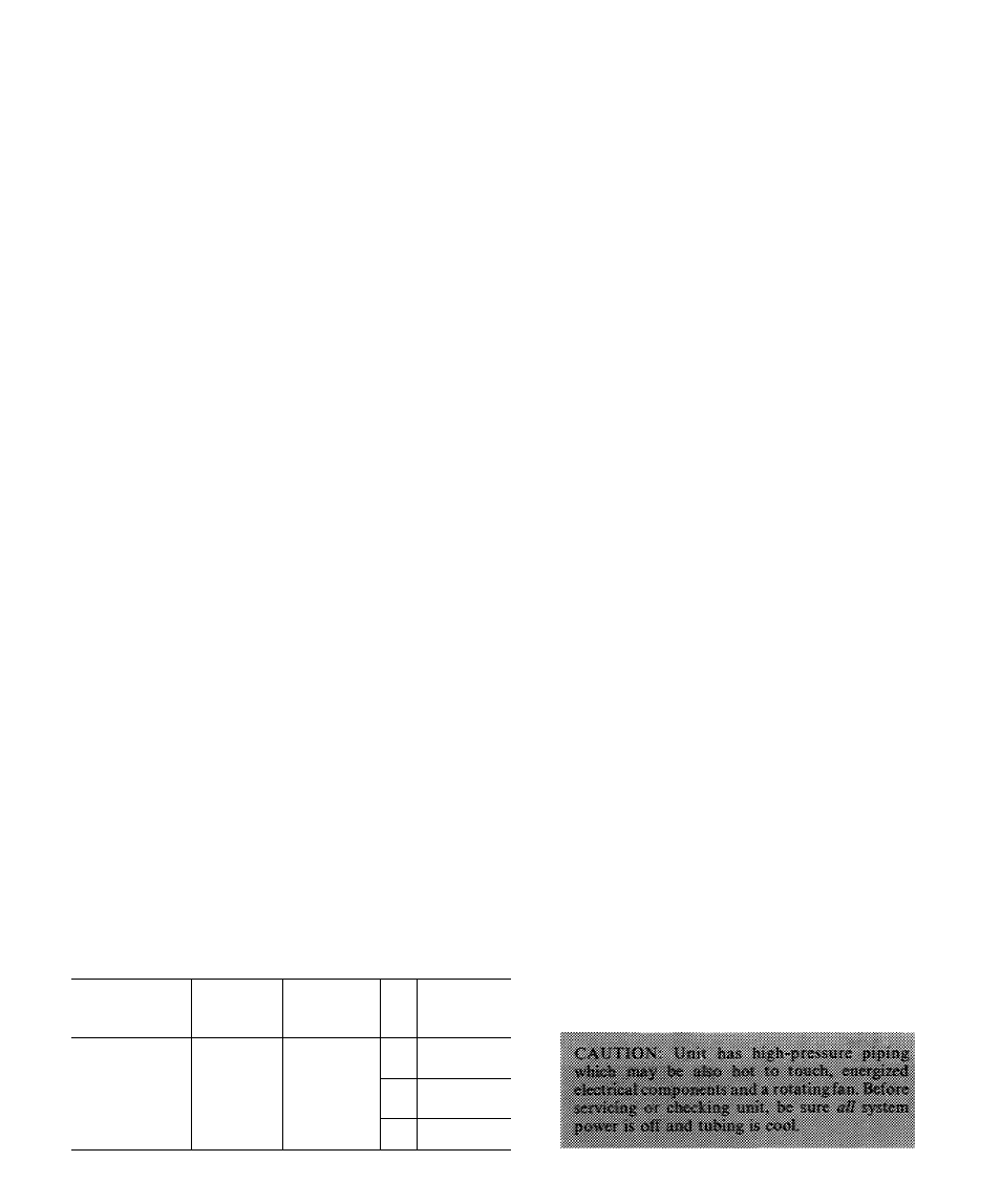
Table 5 — Thermostat Anticipator Settings
UNIT
38Qa
FIRST-
STAGE
ANTICIPATOR
SETTING
INDOOR
UNIT WITH
ELECTRIC
HEATER
HTR
KW
SECOND-
STAGE
ANTICIPATOR
SETTINGS
( 018
\ - , 024
030
036
042
Fixed
40DQ and
40AQ Fan Coil
with 40AQ Htrs
or 40QB Fan Coii
with 40QB Htrs
50
75
100
25
150
20.0
25 0
50
30 0
34.0
75
To Start Unit
— (Make sure crankcase heater
has been energized for 24 hours.) Adjust the thermo
stat as follows:
1. Set selector switch at OFF.
2. Turn on main disconnect switch(es) to indoor
and outdoor units.
3. Set fan switch as desired (ON or AUTO.).
4. Set thermostat dial at desired temperature.
5. Set selector switch at HEAT or COOL.
Check system refrigerant charge. See Refrigerant
Charging.
SERVICE