Compressor removal, Table 8 — compressor data – Carrier 38EB User Manual
Page 8
Attention! The text in this document has been recognized automatically. To view the original document, you can use the "Original mode".
3. Connect Chargemaster outlet port to unit suction
valve service port.
4. Crack valves on refrigerant drum and Charge-
master to purge lines from drum to suction valve.
After purging lines, close valve on Chargemaster
only.
5. Measure outdoor air dry-bulb temperature.
6. Crack unit suction valve and read evaporator
temperature at red needle position on Charge-
master temperature gage and suction line tem
perature at black needle position.
1. Énter Chargemaster Charging Chart, Table 7, at
outdoor air temperature (step 5) and evaporator
temperature (step 6). Find the suction line tem
perature required for correct system charge. If
actual suction line temperature (step 6) is higher
than table value, the system is undercharged. If
suction line temperature is lower than table
value, system is overcharged.
EXAMPLE: At outdoor air temperature of 84 F
and evaporator temperature of 43 F, the system
will be correctly charged at 76 F ± 2 F suction
line temperature. See Table 7.
8. Add charge by slowly opening Chargemaster
valve. If necessary, reduce charge by bleeding at
liquid line service valve. Check outdoor air and
evaporator temperature during procedure. If they
change, refer back to Chargemaster Charging
Chart.
Correct use of Chargemaster ensures that an opti
mum refrigerant charge will be in system when con
ditions and system components are normal.
However, the Chargemaster does not solve or fix
system abnormalities. It indicates correct charge for
condition of the system. It will not make corrections
for dirty filters, slow fans, excessively long or short
suction lines or other abnormal conditions. This
charging device ensures that a correct relationship
exists between outdoor temperature, evaporator
temperature, and suction line temperature on a spe
cific system.
SIGHT GLASS METHOD — (Field-supplied sight
glass installed in liquid line.) A satisfactory oper
ating charge can be obtained on thermal expansion
valve systems only by charging to a clear sight glass.
For optimum charge, increase high-side pressure to
380 ± 10 psig by blocking condenser fan discharge
or air entering condenser. Charge to a clear sight
glass while holding constant high-side pressure. For
peak efficiency, adjust charge to yield a liquid refrig
erant temperature at the evaporator that is approxi
mately the same as outdoor dry-bulb temperature.
r
Table 7 — 38EB Chargemaster® Charging
Chart (AccuRater™ System)
SERVICE
OUTDOOR
TEMP
(F)
EVAPORATOR TEMPERATURE (F)
2TT25l^l3TT34T37^
SucüônUnëT^^
(f )
60
32
40
51
62
30
38
3ê
ta
64
28
37
47
60
66
27
35
45
57
ta
68
34
43
54
67
ta
70
32
41
52
64
72
31
39
50
61
72 1
74
30
37
48
58
69
76
29
36
46
56
66
78
27
35
44
54
63
75
80
26
33
42
52
61
72
82
86
32
29
40
*
37
50
46
59
65
68
63
m
73
85
88
35
44
53
61
70
81
90
34
42
51
59
68
78
90
92
33
41
49
57
65
75
86
94
39
47
55
63
72
83
96
38
45
53
61
70
80
98
36
44
51
59
67
77
100
42
49
57
65
75
102
41
48
55
63
73
104
39
46
53
61
70
106
45
51
59
68
108
43
49
57
65
110
41
47
55
63
112
46
53
61
114
50
59
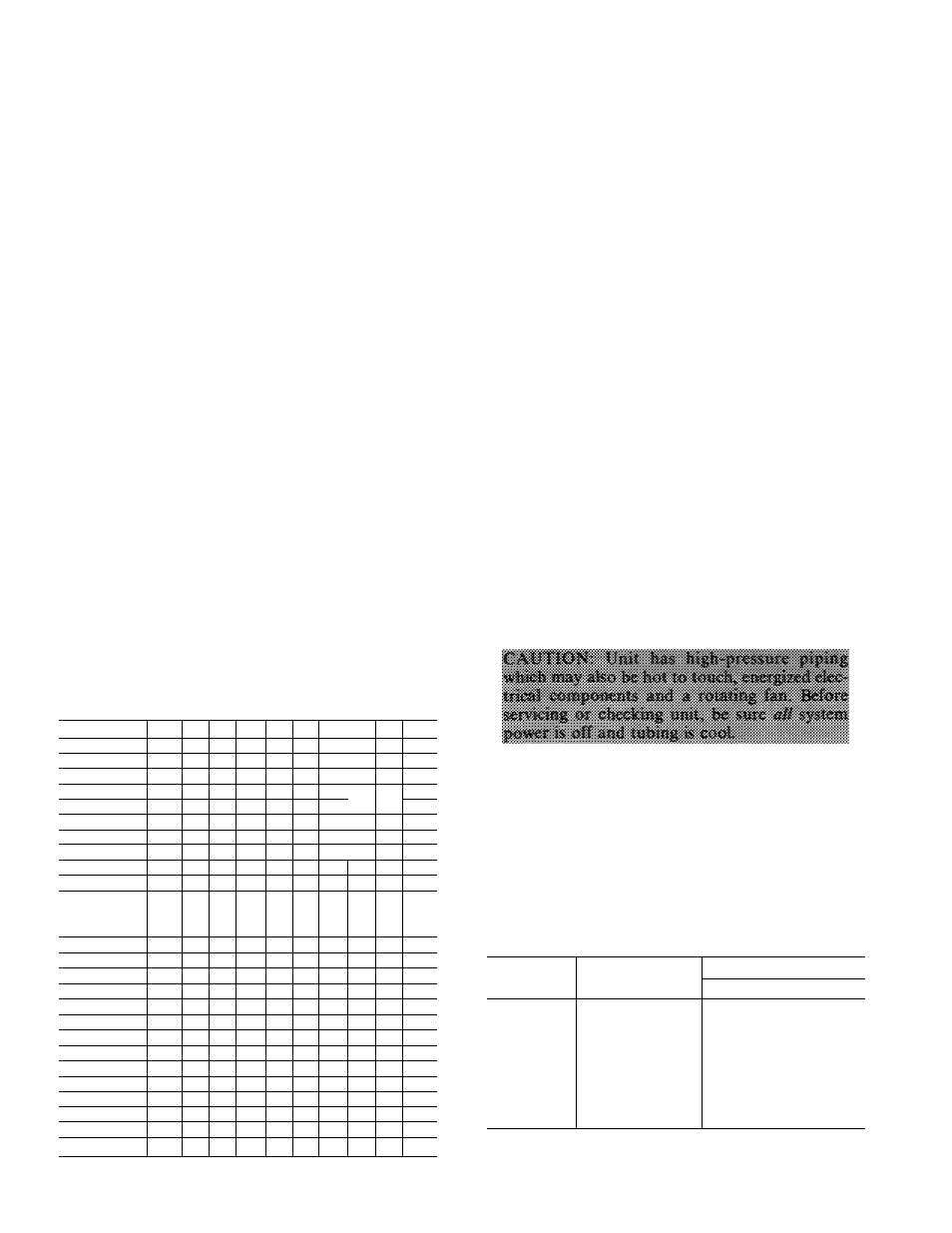
Compressor Removal
— See Table 8 for com
pressor information and Fig. 7 for component loca
tion. Shut off power to unit. Remove refrigerant
from unit using refrigerant removal methods de
scribed in Carrier Standard Service Techniques
Manual, Chapter 1, Refrigerants. Be sure system
pressure is 0 psig before attempting compressor
removal.
■
Table 8 — Compressor Data
UNIT
38EB
PRODUCTION
COMPR*
OIL CHARGE (oz)t
Initial
Recharge
015301
AJ8516G
26
24
018301
AJ8520G
26
24
024301
CRD1-0200PFV
55
51
030301
CRF1-0250PFV
55
51
036301
CRJ1-0300PFV
55
51
042361
AV5542E
54
50
048311
YRD-0400-PFV
72
68
048351
PC5016BD
66
62
060351
PC6416AG
66
62
Example
‘Refer to Carrier Service Parts Catalog for replacement model
numbers
fWhere piping exceeds 50ft, contact your local Carrier distributor