Fig. 5 — control circuit connections, Start-up, Refrigerant charging – Carrier 38EB User Manual
Page 6
Attention! The text in this document has been recognized automatically. To view the original document, you can use the "Original mode".
THERMOSTAT SUBBASE
HH93AZ042 OR
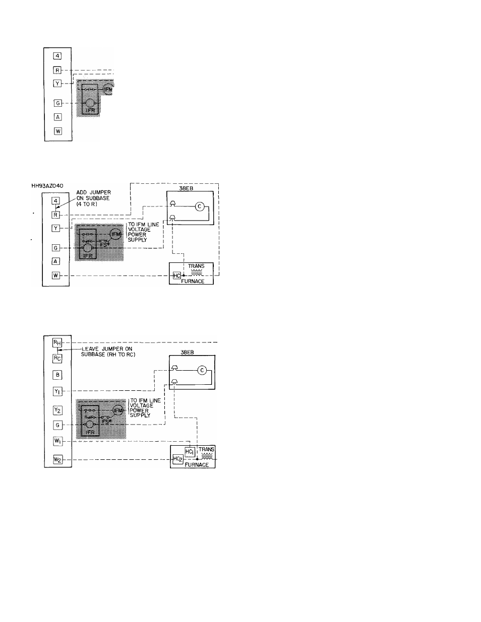
HH93AZ040
38EB
I
- j
TO IFM LINE
VOLTAGE
:}“\POWER
SUPPLY
“©n
TRANS
ARRANGEMENT A-(COOLING ONLY)
THERMOSTAT SUBBASE
ARRANGEMENT B-ONE TRANSFORMER
(COOLING AND ONE-STAGE HEATING)
THERMOSTAT
SUBBASE
HH93AZI76
ARRANGEMENT C-ONE TRANSFORMER
(COOLING AND TWO-STAGE HEATING)
IFR, FS and IFM are located in furnace on heating-cooling
applications If accessory IFR is required for cooling-only
applications, locate (IFR) in fan coil
‘Connect FS to low-speed indoor fan terminal when 2-speed fan
is used
C — Contactor (12-va)
Trans — Transformer
FS — Fan Switch
HC — Heating Control
Field Splice
IFM — Indoor Fan Motor
________ Field Wiring
IFR — Indoor Fan Relay
________ Factory Wiring
NOTE Refer to unit wiring label for wire colors: C to G and C to Y
connections
>• Fig. 5 — Control Circuit Connections
START-UP
1. Backseat (open) liquid and suction line service
valves.
2. Set thermostat selector switch at OFF.
3. Set room thermostat at desired temperature.
Be sure this temperature is below indoor ambient.
4. Close electrical disconnects energizing entire
system.
5. Set room thermostat at COOL and fan switch at
FAN or AUTO, as desired. Operate unit for 15
minutes; then check system refrigerant charge.
See Refrigerant Charging, below.
Motors and controls are designed to operate satis
factorily in the voltage range shown in Table 4. If
necessary to use manifold gages for servicing, refer
to Carrier Standard Service Techniques Manual,
Chapter 1, Refrigerants, page 1-5, Fig. 8 for bypass
method of returning charge to system. Removal of
liquid line charging hose without following these
precautions could result in some loss of charge.
Refrigerant Charging
CAUTION: To
Do sot morchsrge sysiiem. As ovorcbsf®e
cas
Condensing units contain correct operating
charge for complete system when connected to
Carrier-approved evaporators of same capacity as
condensing unit with 25 ft or less of Carrier accessory
tubing or field-supplied tubing of recommended
size. For every 10 ft of liquid line of recommended
size over 25 ft, add refrigerant charge as follows: .41b
for 3/8-in. line; .28 lb for 5/ 16-in. line. On all other
systems, adjust charge for correct operation as
applicable.
Service port connections are provided on liquid
and suction line service valves for evacuation and
charging. See Fig. 1.
TO CHECK, ADJUST OR REPLACE REFRIG
ERANT CHARGE use method recommended in
Table 6. Details of charging methods are listed
below.
Before recharging system, thoroughly evacuate
system and then weigh in refrigerant charge speci
fied in Table 5. Check or adjust charge as required.
Refer to Carrier Standard Service Techniques
Manual, Chapter 1, Refrigerants, for additional sys
tem evacuation and dehydration instructions.
WEIGHT METHOD — Refer to Table 5 or unit
nameplate for correct system refrigerant charge.
Remove any refrigerant remaining in system before
recharging.