Table 6 — refrigerant charging methods, Table 5 — service data – Carrier 38EB User Manual
Page 7
Attention! The text in this document has been recognized automatically. To view the original document, you can use the "Original mode".
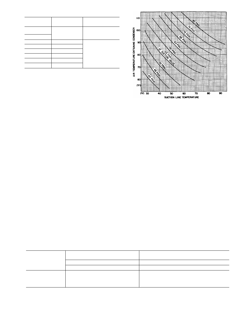
Table 5 — Service Data
UNIT
R-22 CHG‘
CONDENSER
38EB
(lb)
FAN RPM
015300
018300
3 3
1110
024300
030310
5 3
036310
7 5
042360
6 3
048310
6 1
1075
048350
7 2
060350
9 6
‘Factory refrigerant charge is adequate when evaporator and
condensing unit are the same size and are connected with 25ft
or less of field-supplied tubing of recommended size or Carrier
accessory tubing
When system is not evacuated, subtract the
following amount from total charge.
38EB015 thru 030 — .10 lb (1.6 oz)
38EB036 thru 060 — .20 lb (3.2 oz)
The Dial-a-charge charging cylinder is an accu
rate device used to recharge system by weight. These
cylinders are available at refrigeration supply firms.
CHARGING CHART METHOD — Use Charging
Chart, Fig. 6, and the following procedure.
1. Operate unit a minimum of 10 minutes before
checking charge.
2. Measure suction pressure by attaching a gage to
suction valve service port.
3. Measure suction line temperature by attaching a
service thermometer to unit suction line near suc
tion valve. (Insulate thermometer for accurate
readings.)
4. Measure outdoor (condenser inlet) air dry-bulb
temperature with a second thermometer.
5. Refer to Charging Chart (Fig. 6). Find air tem
perature entering condenser and project hori
zontally to curve showing suction pressures
(psig at suction valve).
6. From this interseetion, project vertically down
ward to suction line temperature.
Fig. 6 — 38EB Charging Chart
(AccuRaterT"'' System)
7. If unit has a higher suetion line temperature than
charted temperature, add refrigerant until
charted temperature is reached.
8. If unit has a lower suction line temperature than
charted temperature, bleed refrigerant until
charted temperature is reached.
9. If air temperature entering condenser or pressure
at suction valve changes, charge to new suction
line temperature indicated on chart.
CHARGEMASTER® METHOD — Operate unit
for 10 minutes before using Chargemaster (Carrier
Part No. 38GC680004).
1. Tape Chargemaster feeler bulb to suction line
close to condensing unit. Insulate bulb. Ensure
suction line is clean for good contact with bulb.
(Uninsulated bulb or dirty suction line will seri
ously affect accuracy of temperature readings.)
2. Connect refrigerant drum to Chargemaster inlet
port keeping drum in position for vapor charging.
Table 6 — Refrigerant Charging Methods
COND UNIT
METHODS OF CHECKING OR
ADJUSTING CHARGE
METHODS FOR COMPLETE
RECHARGING
38EB
System Refrigerant Control
System Refrigerant Control
Non TXV j
TXV
Non TXV
1 TXV
ALL
Chargemaster® |
or 1
Charging Chart 1
Sight
Glass‘
Weight Method
plus
Chargemaster or
Charging Chart
Weight Method
1 plus
1 Sight Glass*
‘Sight glass field supplied and installed In liquid refrigerant line.