Unit controls and safety devices, Compatible fitting repair, Condenser fan motor removal – Carrier 38EB User Manual
Page 10
Attention! The text in this document has been recognized automatically. To view the original document, you can use the "Original mode".
Unit Controls and Safety Devices
HIGH-PRESSURE RELIEF VALVE is located in
compressor. Relief valve opens if system operating
pressure differential between suction and discharge
pressure reaches 400 to 500 psi on all models.
LOW-PRESSURE SWITCH (015 and 018 models
only) is located on unit suction line. Low-pressure
switch settings are: cutout, 31 ±4psig; cut-in. 60
(+15, -0) psig.
INTERNAL TEMPERATURE AND/OR CUR
RENT SENSITIVE OVERLOADS reset automati
cally when motor internal temperatures drop to a
safe level (overload may require up to 30 minutes to
reset). When internal overload is suspected of being
open, check by using an ohmmeter or continuity
tester. If necessary, refer to Carrier Standard Serv
ice Techniques Manual, Chapter 2, Electrical, for
complete instructions.
INHERENT FAN MOTOR PROTECTION pro
tects motor from abnormal current and temperature.
SOLID-STATE TIME GUARD II CIRCUIT,
if so equipped, protects unit compressor by prevent
ing short cycling. Time Guard II circuit provides a
5 ± 2-minute delay before restarting compressor
after shutdown for any reason. On normal start-up,
the 5-minute delay occurs before thermostat closes.
After thermostat closes, the Time Guard II circuit
then provides a 3-second delay to prevent contactor
chattering.
CRANKCASE HEATER (when equipped) — The
purpose of the heater is to keep the crankcase warm
during the off cycle and thus prevent dilution of
the oil with refrigerant. This assures good lubrica
tion and prevents loss of oil from crankcase during
start-up.
CRANKCASE
HEATER
RELAY
deactivates
heater when compressor is operating for maximum
energy efficiency.
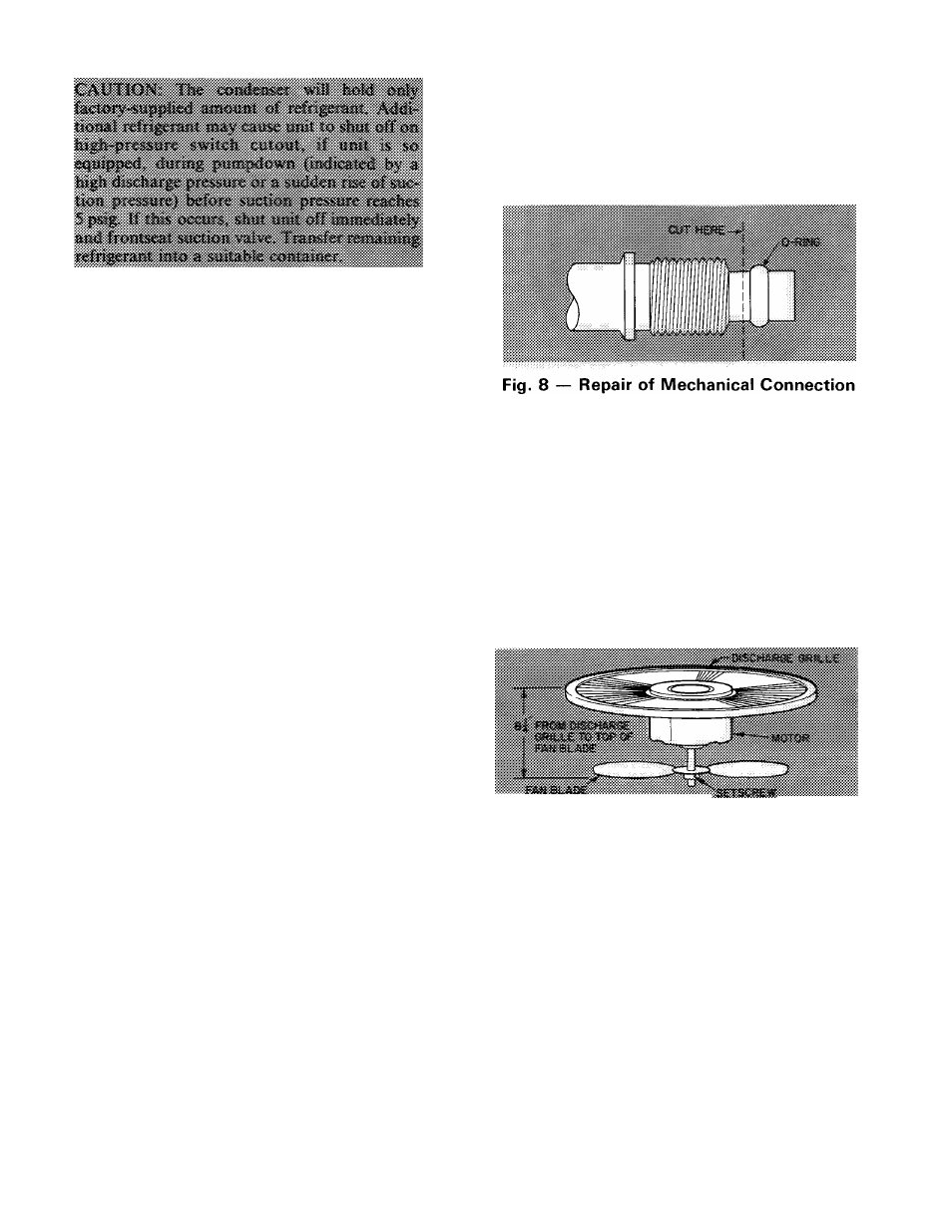
Compatible Fitting Repair
MECHANICAL CONNECTION — Frontseat unit
service valves. Relieve refrigerant pressure from
tubing. Back off locknut from Compatible Fitting
onto tube. Cut fitting between threads and O-ring
as shown in Fig. 8. Remove tubing section remain
ing in threaded portion of fitting. Discard locknut.
Clean, flux, and insert new tube end into remain
ing portion of Compatible Fitting. Wrap valve base
in wet rag. Heat and apply low-temperature (430 F)
solder.
SWEAT CONNECTION — Frontseat unit service
valves. Relieve refrigerant pressure from tubing.
Clean and flux area around leak. Repair using low-
temperature (430 F) solder.
Evacuate or purge evaporator coil and tubing
system. Add refrigerant charge. See Refrigerant
Charging instructions described previously.
Condenser Fan Adjustment
— Required fan
position is shown in Fig. 9. Adjust fan by loosening
setscrew(s) and moving fan blade up or down.
ÎtAAAAfAfVAWA'.
Fig. 9 — Condenser Fan Position
Condenser Fan Motor Removal
1. Shut off power to unit. Failure to do so may
result in electric shock or injury from rotating fan
blade.
2. Remove top cover by loosening 8 screws and
lifting straight up.
3. Disconnect fan motor leads from control leads.
See Fig. 7.
4. Remove 4 screws holding fan motor/discharge
grille in place and lift assembly from unit.
5. Remove Carrier nameplate by straightening
tabs.
6. Remove 4 nuts holding fan motor to discharge
grille. Remove motor and leads.
7. Reassembly is reverse of above procedure. Make
sure fan is positioned correctly as in Fig. 9.
10