Carrier 38EB User Manual
Page 3
Attention! The text in this document has been recognized automatically. To view the original document, you can use the "Original mode".
adapter (Carrier Part No. 28VQ900011) or to cor
rectly sized field-supplied adapter, then make Com
patible Fitting connections.
WARNING: iX> NOT BURY UNESETS- If
fdfigerans
E b. veitkaS Ui« to the vah;« irastxsciioiis
m
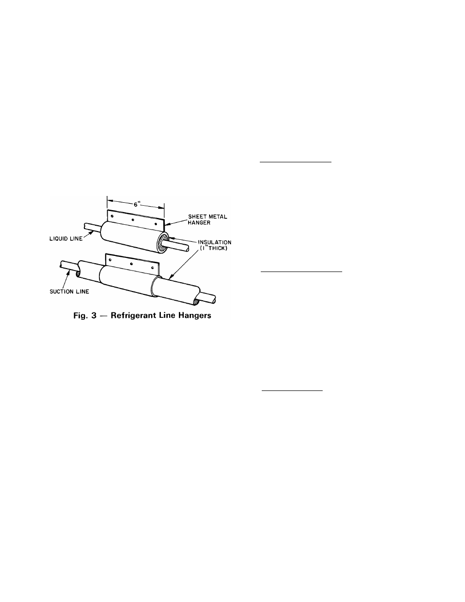
Isolate interconnecting tubing from framing and
ductwork or where tubing runs thru stud spaces, en
closed ceilings or pipe chases. Use isolation type
hanger (Fig. 3) since rigid fastening transmits pulsa
tions to structure creating objectionable sound.
For maximum capacity on 38EB048 and 060 sys^
terns use 1 -1 / 8 in. suction line. A capacity reduction
results if Carrier accessory tubing is used on these
systems. (Example; When a 25-ft accessory tubing
package is used on a 38EB048 system, the smaller
suction line results in a 3% capacity reduction.)
Length of interconnecting tubing may necessitate
refrigerant charge adjustment. Follow special re
quirements described in Start-Up, Refrigerant
Charging, page 6. Do not use less than 10 ft of inter
connecting tubing. On Carrier accessory tubing
packages, do not cut 5/ 16-in. or 1/4-in. liquid line or
7/8-in. suction line. These tubing packages have
swaged ends that, if cut, will not fit into refrigerant
line fittings. Bend or coil excess tubing to fit.
Do not use damaged, undersized or contaminated
tubing. Always evacuate or purge evaporator coil
and tubing system. When purging, use field-supplied
refrigerant, not unit holding charge refrigerant.
When making tubing connections, be sure to pro
vide clearance at unit for electrical connections.
REPLACE
THE
ACCURATER™
REFRIG
ERANT CONTROL PISTON IN THE INDOOR
COIL, if required, before connecting refrigerant
lines. See Carrier Cooling System Capacity Optimi
zation, page 2.
CONNECT REFRIGERANT LINES to fittings on
condensing unit suction and liquid service valves
(Fig. 1). Unit Compatible Fittings permit mechanical
(quick connect) or sweat connections.
Models 38EB048,060 — When using 1 -1 / 8 in. field-
supplied suction line, use field-supplied 3/4-in. by
1-1/8
in.
suction
valve
connection
adapter
(28VQ900011). Sweat connect refrigerant suction
line to 1-1/8 in. end of adapter. Be sure to provide
a heat sink at the service valve to prevent damage
during sweating operation. Connect 3/4-in. end of
adapter to unit suction line Compatible Fitting.
Connect liquid refrigerant line to unit. When a
7/8-in. field-supplied suction line is used, provide a
field-supplied 3/ 4-in. to 7/ 8-in. suction line adapter.
(Not necessary if 38LS accessory tubing is used.)
Mechanical Connection — (Mate one set of connec
tions at a time.)
1. Loosen nut on Compatible Fitting one turn. Do
not remove.
2. Remove plug and be sure O-ring is in the groove
inside the Compatible Fitting.
3. Cut tubing to correct length, deburr and size as
necessary.
4. Insert tube into Compatible Fitting until it
bottoms. Tighten nut until it bottoms on back
coupling flange. Keep tube bottomed in Compat
ible Fitting while tightening nut.
SweatT/onnection — (Use refrigerant grade tubing.-)
1. Remove locking nut, rubber O-ring and Schrader
core and cap from valve service port.
2. Cut tubing to correct length, deburr and size as
necessary.
3. Insert tube in Compatible Fitting until it bottoms.
Wrap top and bottom of service valves in wet
cloth to prevent damage by heat. Solder with low-
temperature (430 F) silver alloy solder.
4. Replace Schrader core and cap.
5. Evacuate or purge system using field-supplied
refrigerant.