Installation, Operation and service, Service kits available – Wilkerson M12 User Manual
Page 2
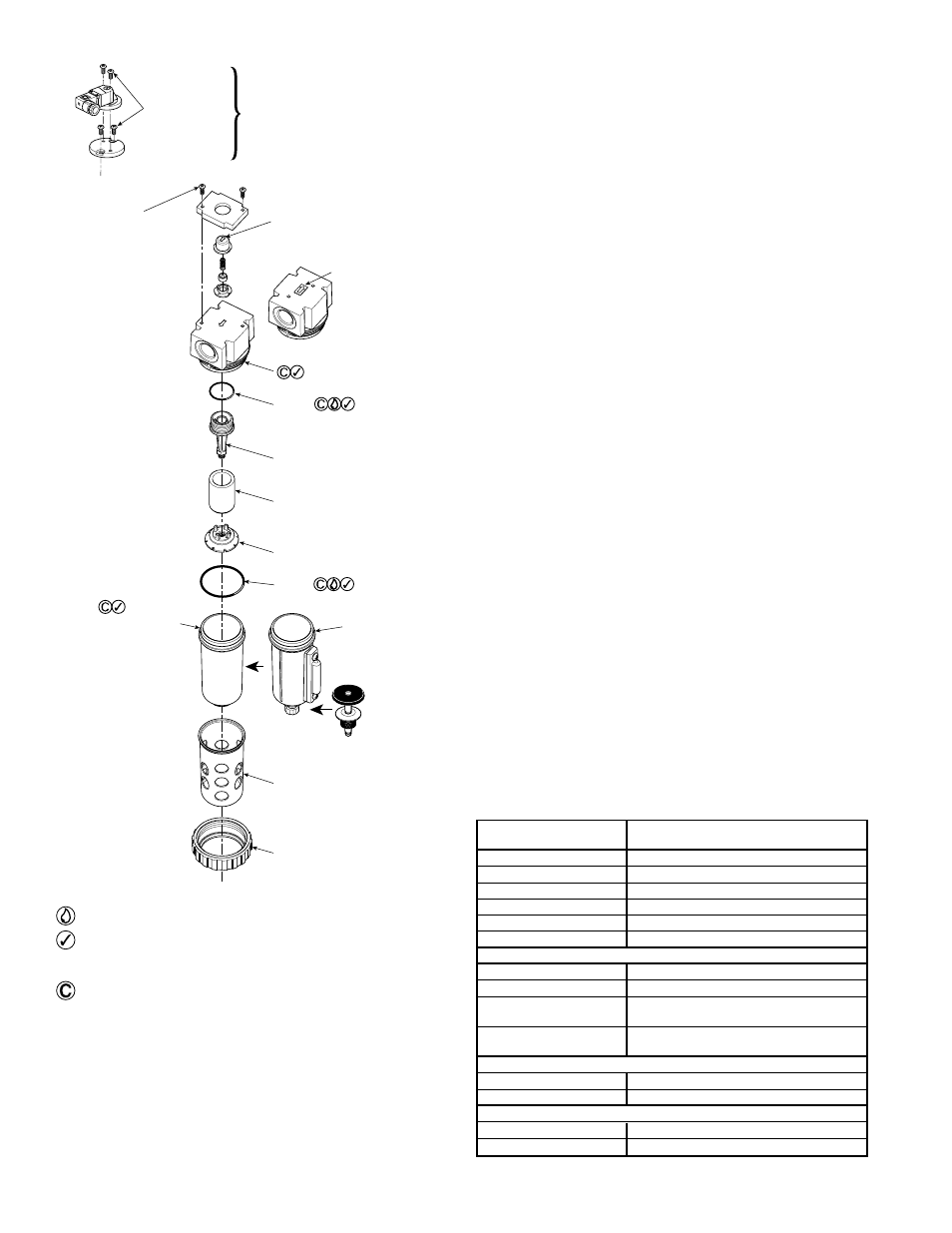
1/4" and 3/8" M12 Coalescing Filter
83-952-000
Installation
1. The filter should be installed with reasonable accessibility
for service whenever possible – repair service kits are
available. Keep pipe or tubing lengths to a minimum with
inside clean and free of dirt and chips. Pipe joint compound
should be used sparingly and applied only to the male pipe
– never into the female port. Do not use PTFE tape to seal
Filter Body
Note Orientation Of All
DPI Parts When
Disassembling & Assembling
(DPI Arrow Opposite
Body Arrow)
Coalescing Filters
Without DPI Only
O-ring
(Locate At
Bottom Of
Threads)
Filter Holder
(Hand Tighten)
Element
Baffle
(Hand Tighten)
O-ring
Bowl Guard
Retaining Collar
(Hand Tighten
Plus 1/4 Turn)
Metal Bowl
(Sight Glass
Shown)
Polycarbonate
Bowl
(See Warning)
(Do Not Scratch
Internal Surfaces)
Manual
Drain
Torque:
0.5 - 0.6 Nm
(4.7 - 5.3 in-lbs)
Torque:
0.5 - 0.6 Nm
(4.7 - 5.3 in-lbs)
Piston
Drain
Optional Electronic
Differential Pressure
Indicator
Using a straight blade
screwdriver, adjust clockwise
to increase differential /
counter-clockwise to
decrease differential.
pipe joints – pieces have a tendency to break off and lodge
inside the unit, possibly causing malfunction. Also, new pipe
or hose should be installed between the filter and equipment
being protected.
2. The upstream pipe work must be clear of accumulated dirt
and liquids.
3. Select a filter location as close as possible to the equipment
being protected and upstream of any pressure regulator.
4. Install filter so that air flows in the direction of arrow on body.
5. Install filter vertically with bowl drain mechanism at the bottom.
Free moisture will thus drain into the sump “quiet zone” at
the bottom of the bowl.
Operation and Service
1. Both free moisture and solids are removed automatically by
the filter. There are no moving parts.
2. Manual drain filters must be drained regularly before the
separated moisture and oil reaches the bottom of the lower
baffle.
3. The coalescing filter element should be removed and replaced
when pressure differential across the filter is 10 psid. The
differential pressure indicator, located on top of the filter
body, gives a visual indication of the pressure differential
across the filter element. Change the filter element when
half or more of the orange piston is above the retaining ring
when air is flowing. For units without a differential pressure
indicator, pressure differential gauges should be used to
determine when the maximum recommended pressure
differential has been reached.
4. Shut off air supply and depressurize the unit before servicing.
5. After servicing, apply system pressure and check for air leaks.
If leakage occurs, Do Not Operate — conduct servicing again.
Service Kits Available
M12
Description
1/4" & 3/8"
Type “B” Element*
MRP-96-301
Type “C” Element*
MRP-96-300
Bowl Guard Kit
GRP-96-345
DPI Repair Kit
FRP-96-300
Electronic DPI Kit
FRP-96-302
Sight Gauge Kit
GRP-96-346
Metal Bowl Kits
Manual Drain
GRP-96-348
Piston Drain
GRP-96-353
Sight Gauge &
GRP-96-349
Manual Drain
Sight Gauge &
GRP-96-352
Piston Drain
Polycarbonate Bowl Kits
Manual Drain
GRP-96-347
Piston Drain
GRP-96-351
Drain Kits
Manual Drain
GRP-96-340
Piston Drain
GRP-96-354
*Element kits include body / bowl seal.
Lightly grease with provided lubricant. (Silicone free)
Inspect for nicks, scratches, and surface imperfections.
If present, reduced service life is probable and future
replacement should be planned.
Clean with lint-free cloth.