USL JSD-60 Manual User Manual
Page 51
Page 51
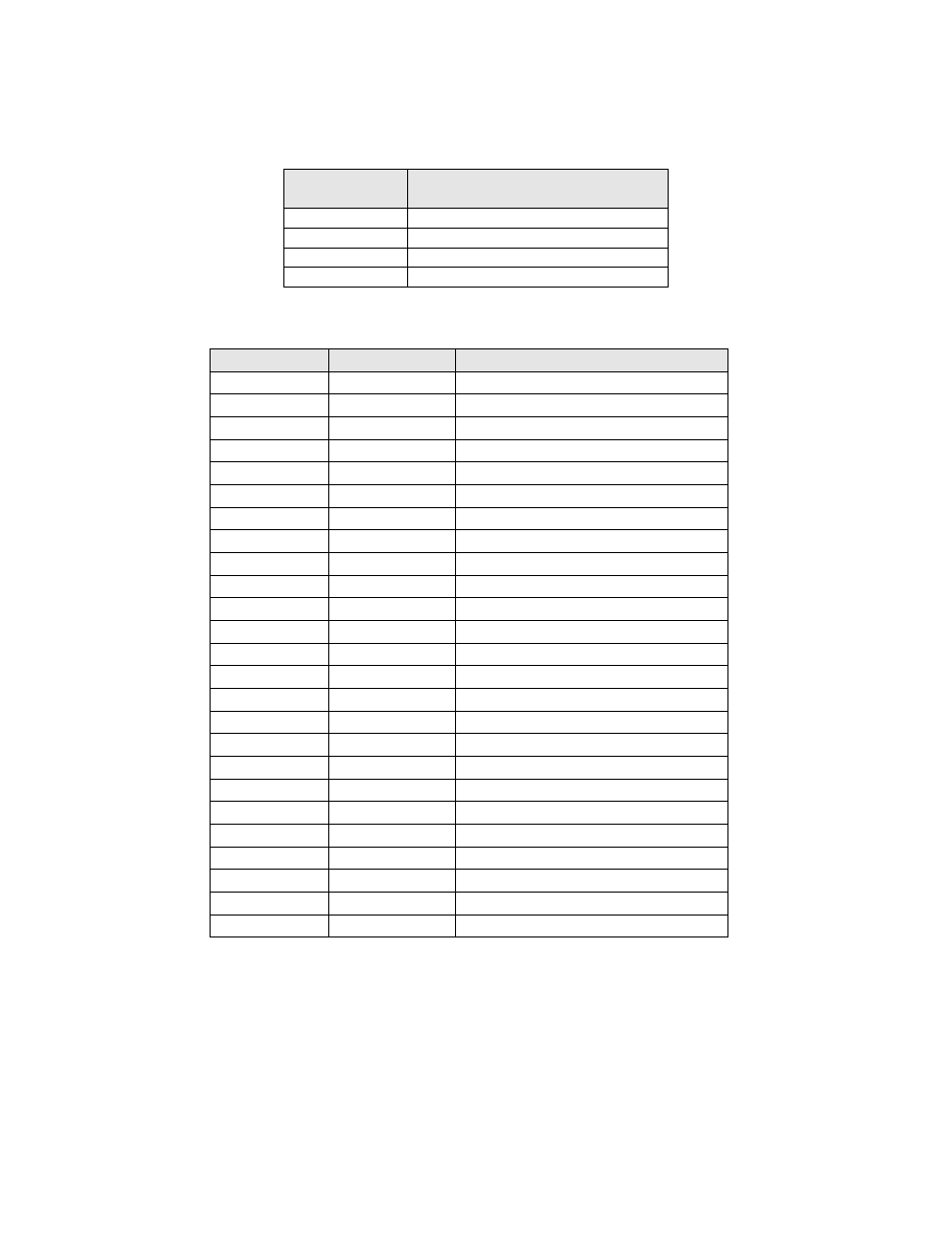
Signals Listed By Channels
Audio Channel
DB25M Crossover
Output Pins (+, -, shield)
Left High
2, 14, 1
Center High
5, 17, 4
Right High
8, 20, 7
LFE 2
25, 12, 13
Signals Listed By Connector Pins
DB25F Pin Out
Signal Name
Channel Name
1
GND
2
Lh+
Left High+
3
4
GND
5
Ch+
Center High+
6
7
GND
8
Rh+
Right High+
9
GND
10
11
12
LFE2-
Low Frequency Effects 2-
13
GND
14
Lh-
Left High-
15
GND
16
17
Ch-
Center High-
18
GND
19
20
Rh-
Right High-
21
22
GND
23
24
25
LFE2+
Low Frequency Effects 2+
HI/VI-N Outputs
The JSD-60 has balanced HI and VI-N outputs that can drive balanced or unbalanced loads. As with other outputs,
the use of twisted pair shielded cable is suggested whether the load is balanced or unbalanced. When driving an
unbalanced load, connect the “ – ” output of the JSD-60 to low side of the unbalanced input at the destination end
of the cable to minimize ground loop noise. The source of audio to drive the HI and VI-N outputs is configurable on
a per-format basis. The VI-N audio output is typically driven by AES/EBU input 8. The HI audio output is typically
driven from a main audio mix.