Plan installation (cont.) mounting options, Mounting options, Converting from right-angle to inline – Twin City Inline / Cabinet Ventilators - TL Series User Manual
Page 14: Page 2
MODELS • T2000L • T3500L
Page 2
PLAN INSTALLATION (cont.)
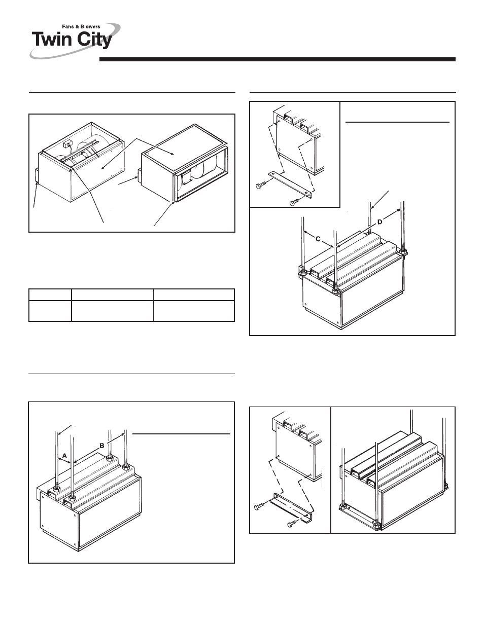
MOUNTING OPTIONS
For correct intake and exhaust duct size, see Table 1.
TABLE 1
ACCESS
PANEL
INTAKE DUCT
FLANGES
EXHAUST
DUCT FLANGE
EXHAUST
DUCT FLANGE
3/8” MIN.
THREADED RODS
(By Others)
DIM. T2000L
T3500L
C
12-5/8”
12-5/8”
D
39-5/8”
47-3/8”
3/8” MIN. THREADED RODS
(By Others)
DIM. T2000L
T3500L
A
7-3/4”
10-1/4”
B
33-3/4”
41-3/4”
Mounting brackets can be bolted to housing ends in a variety of
configurations. Use screws and nuts provided in parts bag.
If installing unit as a ceiling ventilator, make sure that either duct
flanges or housing will be flush with finished ceiling. Duct flanges
may be removed and discarded if they interfere with a ceiling in-
stallation.
MOUNTING OPTIONS
MODEL
INTAKE DUCT SIZE EXHAUST DUCT SIZE
T2000L
12-3/8” x 35-3/4”
7-3/4” x 33-3/4”
T3500L
14-1/2” x 43-1/2”
9-3/4” x 41-3/8”
Provide solid support to minimize sound leves. There are two basic
mounting methods for these units.
Remove and reverse duct flanges and access panel
positions on housing.
Typical mounting with threaded rod through
mounting channels on top of housing.
Mounting with threaded rods through adjustable
mounting brackets located at bottom of housing.
Mounting with threaded rod through adjustable
mounting brackets located at top of housing.
Converting from Right-Angle to Inline