Twin City Backward Inclined Hinged Restaurant Exhaust Fan - BHRE - IM-610 User Manual
Page 2
2
Twin City IM-610
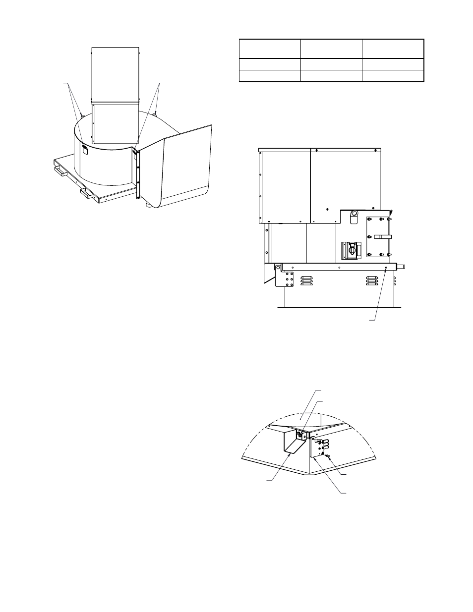
Fan
Nut, 1/2-13
Hinge Bracket
(Both Sides)
1/4-11 x .75 Dril-flex screw or equal
6 Locations
Curb Stop
All hardware found in package HWPACK-1
Lifting Lug
Lifting Lug
Figure 1.
Handling
Lift fan using all lift points. Use spreader bars to ensure
straps do not come in contact with unit. See Figure 1.
Installation
Refer to Table 2 for appropriate size roof opening.
Follow curb manufacturer's recommended installation.
1. For lifting locations, see Fig. 1.
2. Position the fan with its wiring conduit in line with
the wiring or external disconnect, towards the power
supply. The location and placement of any supply
fans should be considered.
3. Center fan on roof curb, allow 3/4" (19 mm) space
all around.
4. Attach hinge bracket to fan with 1/2" cap screw and
nut. Adjust curb stop (bolted to fan) so hinge is
flush with roof curb.
5. Rotate hinge bracket such that mounting holes are
vertical and fasten curb hinge with hardware pack
(p/n HWPACK-1) according to Fig. 3.
6. Screw fan to the roof curb using #12-14 dril-flex or
equal 3" (76 mm) from each corner and one fas-
tener centered. Add additional fasteners equally
spaced to satisfy. See Figure 2 and Table 1.
7. Verify the power is de-energized. Run wires to the
disconnect switch. Leave some slack in the wire in
the motor compartment so the motor and wheel
assembly can be lifted for inspection and cleaning.
8. Verify power source is compatible with the fan.
Make connection to the disconnect switch.
9. Check tightness of all fasteners.
10. Verify wheel is centered and spins freely.
11. Restaurant fan installation must be in compliance
with local codes and National Fire Protection
Association's standard NFPA 96.
Table 1. Fan Mounting to Roof Curb
BHRE Size
Fasteners per
Side
Total
Fasteners
105
2
8
122 - 245
3
12
#12-14 Dril-Flex self drilling
screw or equal
Figure 2.
Figure 3.