Top Flite Phasoar 035 User Manual
Page 9
2. Glue 1/4" triangular corner blocks, leaving
space for F-3 at forward edge of fuselage.
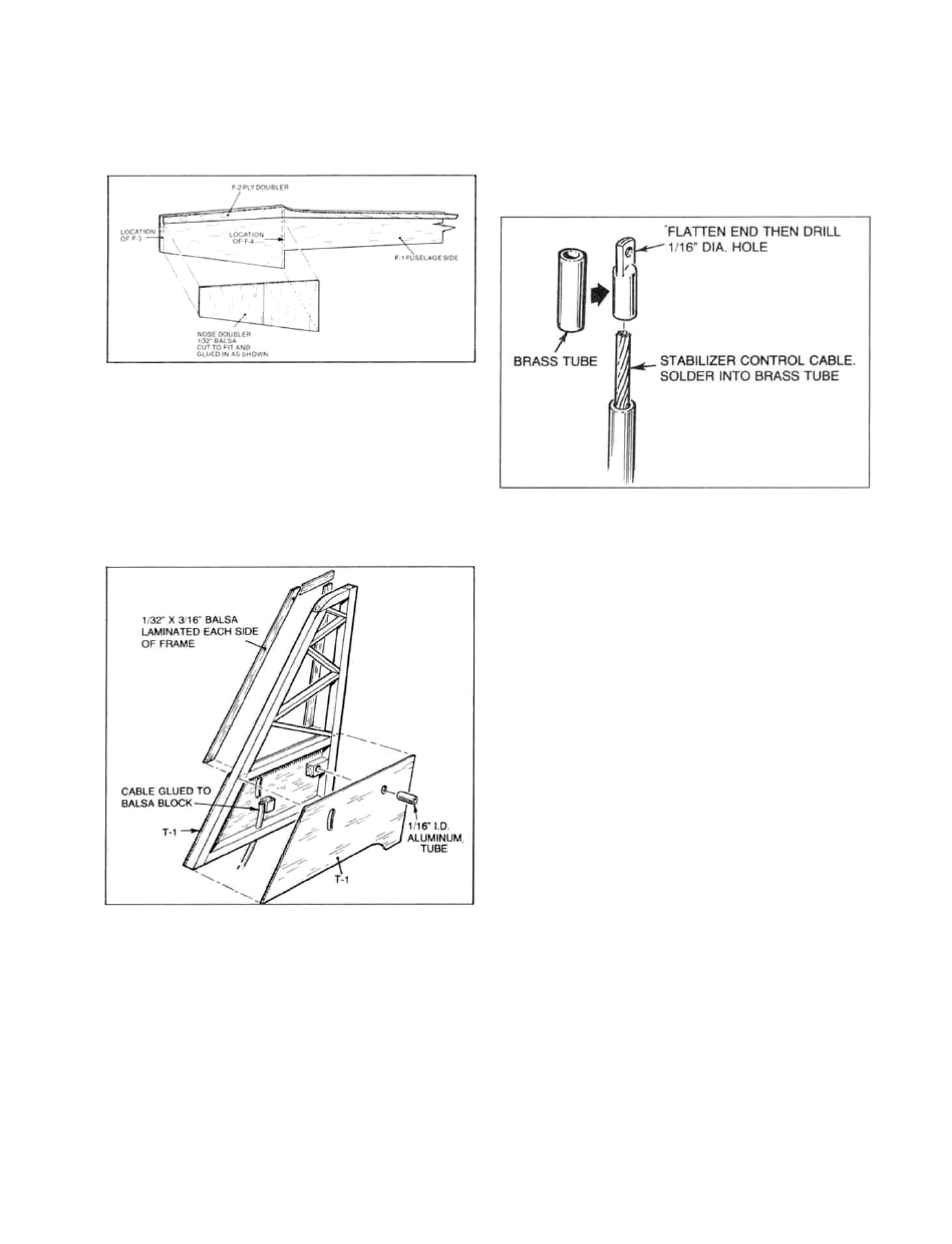
Using F-3 and F-4 for spacing, cut and glue
1/32" v e r t i c a l - g r a i n nose doublers.
3. Add 1/8" longerons and uprights per
sections E-E, F-F, and G-G.
4. D r i l l LEFT fuse side for rudder control
tube exit as shown, glue tube in place to
inside of left side a l l the way to F-5
(about every 1") - set aside.
5. Build basic fin frame directly over plans
using 3/16" x 3/16" outside frame stock.
Remove from plans; lightly sand flat.
Glue block in place to RIGHT T-1, just
below cutout. Insert cable into tube and
use a heat gun to bend tubing and cable to
fit w i t h i n right fuse side. Once bend has
been made, glue tube to right fuse side up
to F-5 location about every inch.
Install antenna tube
(sections E-E and F-F).
to right side
6. Glue RIGHT fin sheet part T-1 accurately
in place, as shown on fin drawing. Glue
rear 3/16" Sq. pivot block in place. Glue
RIGHT side 1/32" x 3/16" fin frame cap
stock in place; l i g h t l y sand flat. Glue
fin in place to RIGHT fuselage side, over
plans.
7. Solder drive fitting to cable end. Use
3/16" x 3/16" block to hold cable tube.
8. Notch F-5 to accept rudder, elevator, and
antenna tubes. Notch F-4 to accept rudder
and elevator tubes.
9. Mark rear pivot hole location onto LEFT T-
1 side. Use a punch (nail, etc.) to open
this hole enough so that later sanding
won't remove it. Glue LEFT T - 1 sheet in
place. Use the 1/32" x 3/16" stock to cap
the left side of the fin. Lightly sand
flat.
10. Lay the LEFT fuselage side over the RIGHT
fuselage side/fin assembly. Check fit.
Sides should match. Glue LEFT fuse side
to R I G H T fuse side from 1" forward of the
fin, back to the end of the fuselage -
weight or pin and allow to dry.
11. Spread fuse sides and glue F-5 in place -
keep square (5-minute epoxy allows a bit
more positioning time. Glue F-4 in place;
keep square.
12. Glue rear 1/8" ply screw plate in place
against F-5 fuse sides and against bottoms
of F-2.
13. Epoxy F-3 in place.
14. T r i a l - f i t motor, with the ASTRO FLIGHT
Cobalt 035, rotate motor as far as it w i l l
go to the right (this minimizes the height
of the brush housings). Note that the
bottom brush housing w i l l contact the
9