Top Flite Phasoar 035 User Manual
Page 8
2. Cut, fit and glue the rudder's 3/16" sq.
balsa leading, top and t r a i l i n g edge in
place. Glue one of the RC-1's in place
directly over the R - 1 / R - 1 structure,
matching each edge. Locate and remove two
of the die-cut 1/32" x 3/16" x 8-1/2" fin
and rudder cap strips from their sheet. As
shown on the plans, the cross-hatched areas
at the leading edge and top of the rudder
are "capped" with this capstrip stock - do
this now. Remove the structure from the
plans and l i g h t l y sand the "capped" side
smooth. Place the structure back on your
work surface, opposite side up, and glue
the remaining RC-1 and capstrip stock in
place. Again, l i g h t l y sand this side of
the rudder smooth. Re-position the rudder
assembly in place over the plans - pin or
weight.
3. Using the 1/4" sq. balsa stock provided,
cut, f i t and glue the two bottom, leading
and t r a i l i n g edge corner gussets in place.
Using the 3/32" x 1/4" balsa provided, cut,
f i t and glue the diagonal geodetic "ribs"
in place, using the plans as a guide.
Again take care to create the best joints
that you can.
4. Remove the rudder structure from your work
surface and use a sanding block to smooth
each of the four outer edges and the left
and right surface of each side. with the
exception of the addition of the 1/32" ply
rudder control horn and the 45-degree bevel
for hinging, the rudder is now complete and
can be sanded to the shape shown on the
plans. Set the structure aside for later
fitting to the fin.
X. FUSELAGE/FIN CONSTRUCTION
Note that the fuselage and fin, with the stabilator
drive, are constructed as a single unit.
1. Remove the two fuselage sides from their
die-cut sheet. Tape, pin or clamp them
together and use a sanding block to l i g h t l y
sand their edges, thus matching them
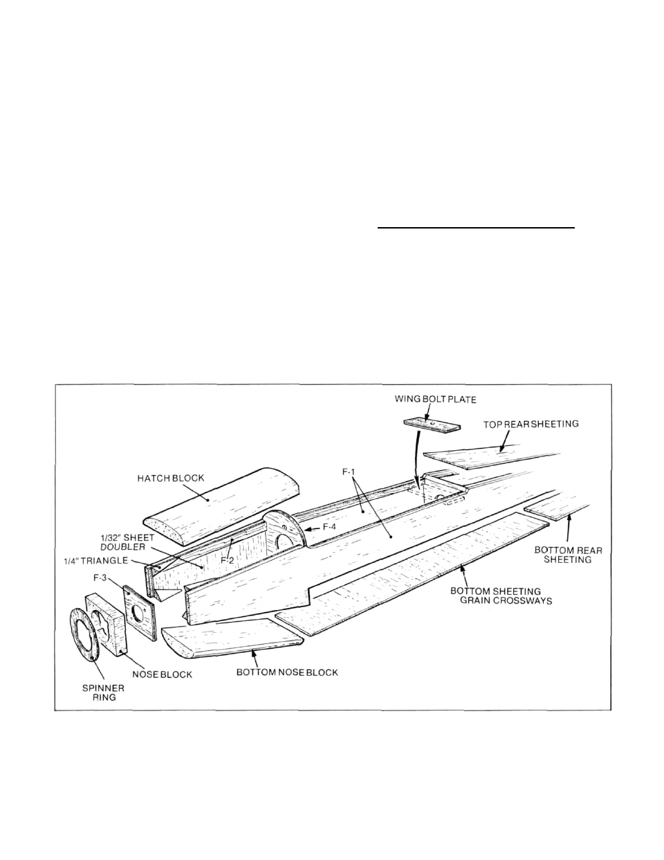
exactly. Remembering that a left and right
side is required, glue F-2 on the fuselage
sides as shown below on the assembly of
nose and forward fuselage drawing.
8