Top Flite Phasoar 035 User Manual
Page 12
the fuselage. Use your sanding block to
now sand the top, rear sheeting and the
forward radio hatch and nose block piece
flush w i t h the fuselage sides. You can
also now sand the top forward hatch and
nose-block contours to shape as shown in
the plans, no need to round corners yet.
28. From your parts bag, locate the 1/4" shaped
fin/fuselage fairing. Use your sanding
block to adjust the angles if needed and
glue in place. As shown, this is now
trimmed to fair the fin leading edge into
the top, rear of the fuselage.
29. Finally, push the 1/4" length of aluminum
tubing that's in the rear pivot hole about
halfway out, apply just a bit of adhesive
to its outer surface (5-minute epoxy or
slow-cure CA) and push i t back in place in
the fin.
30. with the exception of contouring and final
sanding, your fuselage should be complete.
XI. FINAL ASSEMBLY
It's often been said that the difference between a
good model and a great one is sandpaper and the
willingness and a b i l i t y to use it. This point in
construction can l i t e r a l l y make or break the
performance and the look of your model. Since the
PHASOAR is an obvious candidate for use of
MonoKote, keep in mind that the surface preparation
of the wood w i l l dictate the finished, covered look
of your model. Referenced use of " f i l l e r " in the
following text. refers to products such as
M i c r o F i l l , Model Magic F i l l e r , or something
similar. These products dry quickly, are very
light, and MonoKote goes over them nicely.
Let's start w i t h the fuselage, since the other
components should, by now, be sanded and about
ready to use.
1. Note the lower left corner of Cross Section
F-F on the plans. This demonstrates about
the correct amount of radius that can and
should be sanded into the fuselage bottom.
As this sanding radius moves aft, toward
the fin post, and the fuselage diminishes
in width, the result w i l l be a pleasant
looking oval shape. Next, sand the radio
hatch and nose sections. Use a rougher
grit of paper at first, followed by the
finer #220 to do the job nicely. The last
section to tackle is the top, rear of the
fuselage - back and including the fin
fairing and f i n leading edge. Take every
effort needed to sand this structure to the
point that it looks and feels l i k e one
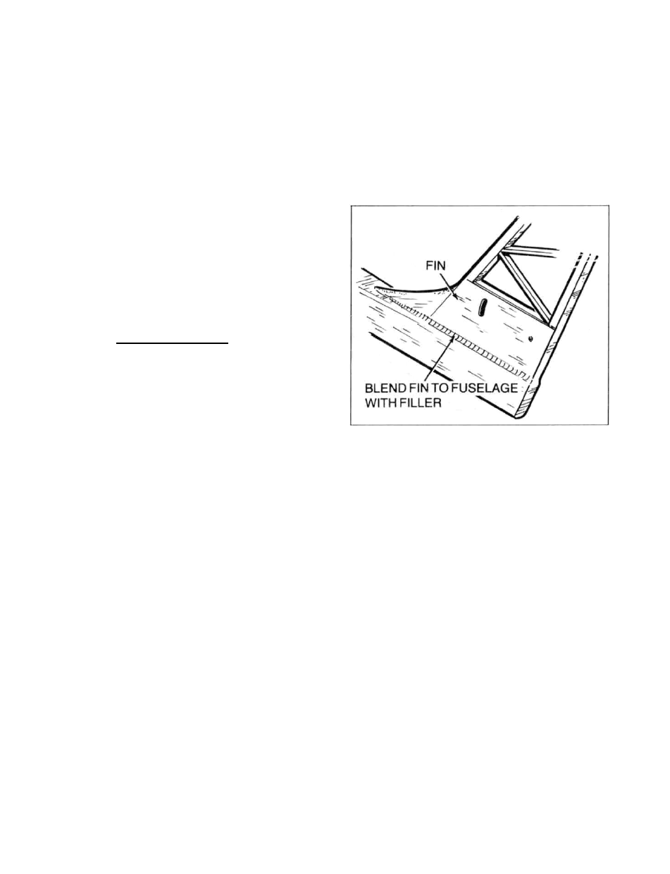
piece. You w i l l note that where the T-1
fin sides meet the fuselage sides, there is
a disparity in wood thickness resulting in
a kind of "tip." On our prototypes we
handled this by sticking a length of
masking tape lengthwise about 3/16" above
this joint, on T-1. Then we carefully
sanded down the fuselage side(s) to as
close to T-1 as possible (the masking tape
was there to protect T - 1 in case we got too
close). Then with the tape s t i l l in place.
we used f i l l e r to "fair-in" this joint,
feathering the material carefully. When
the f i l l e r was dry, the tape was removed
and we used very light sandpaper to finish
feathering the joint.
2. Use your sanding block to sand the trailing
edge of the f i n f l a t and straight.
3. The last step in preparing the fuselage for
covering is to sand the fin/rudder
combination together, as a single unit.
Start by using masking tape to accurately
position the rudder to the fin. Now use
your sanding block to accurately match the
side view shape of the rudder to the
fin/fuselage. Once that's done, remove one
of the pieces of tape from one side only
and lay the structure down on a flat
surface - taped side down. Use your
sanding block to now sand the rudder's
cross-section shape into the fin/fuselage,
but only about halfway. Add another piece
of tape to the now sanded side, f l i p the
structure over, remove the tape and repeat
the sanding operation. After a couple of
passes on each side, you should be about
where you want to be; a fin w i t h a true
leading edge and a rudder with a true
t r a i l i n g edge and everything in between
accurately matched. The leading edge of
the rudder can now be beveled as shown on
the plans, thus f a c i l i t a t i n g left and right
movement when hinged w i t h MonoKote.
Once this is done, locate and remove the
1/32" ply rudder horn from its die-cut
12