Top Flite Holy Smoke User Manual
Page 6
the cable/tube assembly around to the exit point
shown at the aileron horn location. Use a marking
pen to note the location of the tube on each rib.
Repeat this operation for the opposite wing panel.
Again, use the 1/8" drill bit to drill holes through the
W-2's and W-3's that will allow the tubing to pass.
Now use a piece of sharpened 1/8" dia. tubing to
make the tubing exits, at the angles shown, through
the bottom, rear planking. With the cables still in-
side the tubes, feed the tubes through the various
holes until they exit. Test the action of the cables;
movement should be free and easy. Once satisfied,
use slow setting CA to anchor the tubes in place to
the ribs and planking. Trim the aileron exit tube ends
flush with the planking—remove the cables and set
aside for installation when the airplane is finished.
24. You should have about 15"-16" of white tubing left
over from the antenna tube; this will be used for the
nosegear steering cable. As shown, this cable is
driven by the opposite end of your servo's output
arm. Locate the remaining 12" length of braided
cable and solder the brass coupler in place. Thread
one of the black nylon mini-links in place on the
coupler. This will be the servo end of the steering
cable. From your planking stock (3/32" balsa), cut a
2-7/16" x 3-7/8" rectangle and glue this in place on the
W-1 ribs and flush with the front face of W-9. You
should wind-up with a little of the W-1's thicknes still
exposed on each side to allow seating for the rest of
the bottom planking—fit this piece carefully. As
before with the aileron tubes, drill a 1/8" dia. hole
through the right-side W-1 at the correct position for
the servo's output arm to drive the steering cable.
Slip the cable into the tubing and hold it in position
over this hole, again, you might have a friend hold it
there for you. Now gently bend the cable/tubing as
shown on the plans around towards the nose to the
exit point shown. Use a marker to note the passage
point through W-1 at the front. Use a drill bit to drill
the hole through W-1 and a sharpened piece of tub-
ing to make the exit hole through the planking just in-
stalled. Install the tubing through all three holes and
test the action of the cable, as before, it should be a
free fit. Adjust the tubing to obtain the optimum
movement and glue it in place. Remove the cable
and the aileron servo. Trim the tubing flush with the
planking.
25. The balance of the bottom planking can now be in-
stalled. In order to find and clear out the landing gear
skid slots later, use a straight edge and pencil to
make horizontal and vertical reference marks on the
sheeting already in place. Note that the hatch area is
left open with the inboard ends of the planking trim-
med flush with the inboard faces of the W-1's. All
that should remain after planking is the open hatch
area and the nose bottom.
26. From the kit, locate the four blocks required to fill-in
the bottom nose area; 2 @ 1" x 1-1/2" x 5-1/2" balsa; 1
@ 3/4" x 1" x 3-1/2 " balsa and 1 @ 3/4" x 1-7/8" x 2"
bssswood. The hardwood block is used to mount the
5/32" dia. coiled nose gear. The two 1-1/2" wide balsa
blocks fit on the outside edges of the W-1 's, against
the W-7 ply floor and against the face of W-9. The re-
maining 3/4" wide block fills in the remaining slot.
Use your sanding block as needed to achieve a good,
flush fit of these four blocks. Use a drill press to drill
a vertical 5/32" dia. hole through the hardwood block
at the position shown on the plans for the nose gear.
Glue all four blocks in place. After the glue has set,
chuck-up the 5/32" dia. drill bit in a hand drill and com-
plete the hole in the hardwood block all the way
through the floor, into the engine compartment.
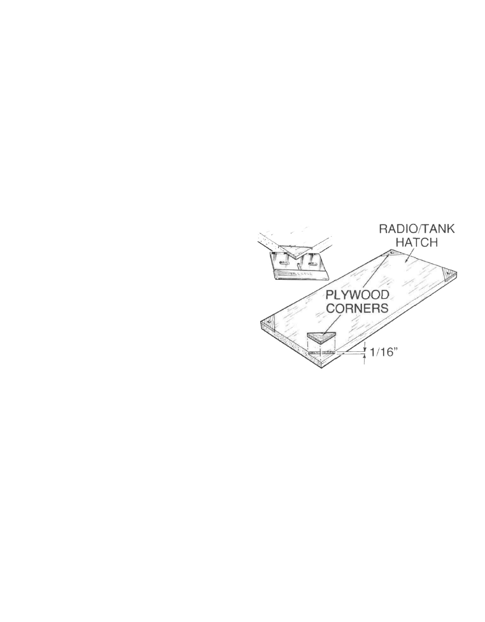
27. The radio compartment hatch supplied in your kit
measures 1/4" x 3 - 3 / 4 " x 9" and is balsa. It is mounted
to the four 1/2" sq. hardwood blocks supplied. Glue
these blocks in place in the four corners of the hatch
opening at a depth which will leave the hatch flush
with the planking. Install the four die-cut ply
triangles that were left from die-cut sheet RC-34-6,
on each corner of the hatch. Use a razor blade to
remove 1/16" of depth of the hatch corners, in the
shape of the ply triangles and epoxy these in place.
Now locate the hatch in position on the four hard-
wood mounts—use tape to hold it there if need be.
With a 3/32" drill bit, drill a guide hole through each of
the four corners of the hatch and in contact with the
hardwood mounts, just enough to leave a mark on
each of the mounts. Remove the hatch and use a 1/16"
drill bit to drill a guide hole through each of the
mounts. Locate four of the #2 x 3/8" wood screws sup-
plied and screw the hatch in place to the mounts.
Once satisfied with the fit, remove the screws and
lightly tack glue the hatch in place to the
mounts—you want to be able to remove it after san-
ding. Using the cross-reference marks made earlier,
use an X-acto knife to clear-out the two rear landing
skid slots.
28. Use a razor blade to first rough shape the upper and
lower nose blocks. Follow this with a sanding block
and coarse sandpaper to bring these blocks down
further. Use the razor plane again to rough shape the
leading edges—refer to cross-sections on the plans.
Finally, the entire wing can be sanded with pro-
gressively lighter sandpaper until ready for cover-
ing. Take your time and get it right. Remove the tack
glued hatch and set it aside for covering.
6