Top Flite Holy Smoke User Manual
Page 4
7. The first piece of planking that you are going to at-
tach will be the rear one which is one-piece from tip
to tip and flush with the bottom 3/32" x 7/8" balsa strip
installed in the rib slots earlier—see cross-sections
on plans. Glue and pin this rear piece of planking in
place to the tops of the ribs and along the trailing
edge of the bottom sheet.
8. The next two pieces of planking to be installed are
those that fit from the the centerline of the spars, for-
ward to the rear face of the landing edges. Trim the
inboard ends to fit flush with the inside faces of the
W-1 ribs and on top of W-9, as shown. Once the plank-
ing pieces are trimmed to fit, use a little ammonia on
their top surfaces to get them to bend easier to fit the
tops of the ribs. Glue these two pieces of planking in
place, pin or weight as needed and allow to dry.
9. Remove W-10 from its die-cut sheet and lightly sand
its edges to fit between the W-1 's at the rear position
shown on the plans. Use a triangle to accurately
locate this former and glue it in place, aligning the
top edge with the tops of the W-1's.
10. Using the left-hand view of the wing (remember,
that's the top planking patterns shown), finish plank-
ing the left and right-hand side of the top of the wing.
Trim the centerline ends of each piece of planking to
provide a true centerline for accurately locating the
fin. Note that the entire left and right center planking
pieces can also be made separately, on a flat sur-
face and then fitted in place on each side of the
centerline. Just be sure that, if you do it this way, you
leave just a little extra material at the rear to trim and
therefore achieve a nice, gapless fit.
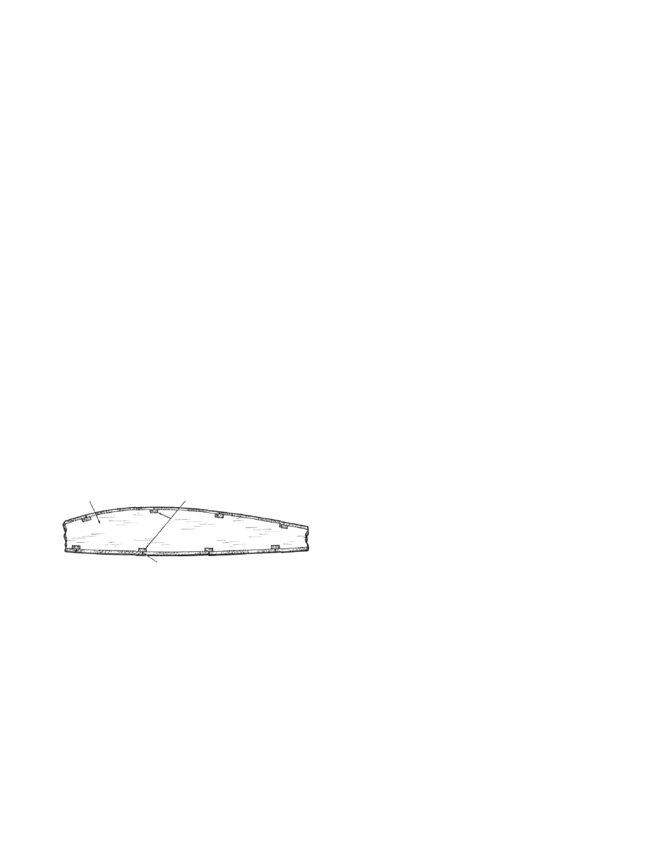
SCRAP 3/32" BALSA STRIPS IN
PLACE BETWEEN RIBS AS "SHELVES"
RIB (TYPICAL) FOR BUTT-SHEETING
SHEETING JOINT
11. Using the 1/4"x3"x36" piece of balsa provided and
the pattern shown on the plans, carefully cut and
glue the four required pieces together to form the
rough shape of the fin. Use a sanding block to finish
the fin into the side-view configuration shown.
Follow this by sanding the fin assembly smooth on
each side and then rounding the leading, trailing and
top edges to a "half-round", as shown. Streamlining
or airfoiling this surface is not needed or desirable.
12. The fin's support tab requires a slot that is 1/4" wide
and 3-1/16" long. This is located on the exact
centerline of the wing. As shown on the plans, the
rear end of this slot is measured at 3-1/16" from the
trailing edge. Cut this slot with a fresh #11 X-acto
blade. The forward end of the slot should be at the
rear face of W-10. Trial fit the fin in place and dress
the bottom edge of it as required to achieve a
uniform fit to the top surface of the wing's planking.
Once satisfied, set aside the fin for later installation.
13. From your parts bag, locate the four 4-40 blind moun-
ting nuts and their corresponding 1-1/4" motor mount
bolts. Also locate the two 3/16" x 3/4" x 5-1/2" maple
motor mounts and the two top 7/8" x 1-3/4" x 5-1/2"
balsa cowl blocks. Before assemblying the motor
mounts and cowl blocks in place as shown on the
plans, let's first trial fit the whole thing on the nose
with your engine sitting in place between the maple
mounts. Is the fit a comfortable one or is it too tight
or too loose? Engines vary somewhat in case width
and if yours happens to be a little too wide, then you
will find that the engine will either not fit at all or a lit-
tle too tight. If this is the case then you must use a
sanding block to remove a little of the width from the
two balsa cowl blocks. Try to do this evenly and a lit-
tle at a time while continually trial-fitting the engine.
Once satisfied, you can move on to the next step. If
your engine fits too loosely between the mounts
then you must add material to the sides of the cowl
blocks to space them out a little. 1/16" sheet balsa on
each block would move the mounts inward 1/8", etc.
14. Glue the balsa cowl blocks in place in the nose
against the inside faces of the W-1's, against the
front face of W-9 and against the W-7 ply floor. Use a
scrap of balsa to scrape out any oozing glue
because we want the maple motor mounts to fit in
place squarely to the floor and the cowl blocks.
Lightly tack glue the two maple motor mounts to the
ply floor only, exactly in the position they will even-
tually be. Set your engine in place on the mounts
with the thrust washer just clearing the front of the
nose (see top view and engine cross-section on
plans). Now carefully mark the lug hole positions on
the motor mounts with a pencil or sharpened object
of some kind. Remove the engine and break the two
motor mounts free from the ply floor. Use a drill
press and a 1/8" dia. drill bit to drill the two required
holes in each motor mount (a hand drill can be used
if you are careful). In order to get the motor mounts to
sit flush against the W-7 ply floor, you must now use
a Moto-Tool and grinder bit to counter-sink the 4-40
blind nuts. Epoxy these nuts in place to the bottom
of each motor mount, being careful to keep glue out
of the nut's threads. Using medium to slow curing
epoxy, glue the mounts permanently in place. When
the glue has cured remove the pins holding the struc-
ture in place to your building board and remove the
wing.
15. Turn the wing over exposing the unplanked bottom
and block-up the nose until the trailing edge lays flat
to your work surface. Use an X-acto knife to carefully
remove the rear building tabs on all of the ribs. This
exposes the forward edge of the bottom trailing
edge strip installed at the beginning. Take one of the
3/32" x 3 " x 36" planking pieces, true-up its edges with
a straight-edge and razor and glue it in place against
the forward edge of the trailing edge piece and
against each rib. (We found that a truer butt-joint
could be made by first gluing scrap pieces of balsa
underneath the piece of balsa planking that was
already in place thus creating a sort of "shelf". The
excess material left over from the die-cut sheets pro-
vides plenty of these shelf pieces.) Pin or weight this
4