Top Flite Holy Smoke User Manual
Page 3
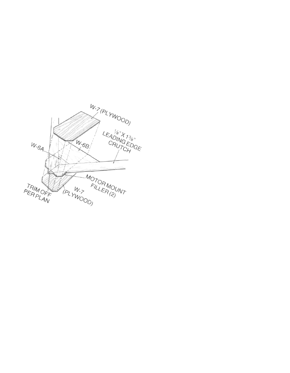
3. Locate die-cut sheet RC-34-1 (2 req'd.) and remove
the two Motor Mount Fillers. These are now glued in
place against the leading edges of the two leading
edge crutches, at the nose, directly behind the spin-
ner shown on the plans. Now use your sanding block
to lightly smooth off the glue joints. From the ply die-
cut sheet RC-34-6, remove the two W-7 parts. Use
your sanding block to clean up their edges. Glue one
of the W-7 parts directly on top of the leading edge
crutch assembly, aligning its rear edge with the rear
edge of W-6B and its forward edges with those of the
two motor mount fillers. Use weights to make sure
that W-7 stays flat against the leading edge crutch
assembly until it is dry.
4. Remove the leading edge crutch from the plans, turn
it over and use your sanding block to smooth out any
glue joints. Glue the remaining W-7 part in place to
the bottom surface of the crutch assembly, exactly
aligned with the W-7 previously glued to the top sur-
face. Again, use weights to hold this part in place
and allow it to dry.
Remove this assembly from your building board as
we will now build the rest of the airplane.
GENERAL CONSTRUCTION
1. From the die-cut sheets provided, carefully remove
all of the required wing ribs W-1 through W-5, two of
each. Note that these ribs each have temporary
"tabs" attached to the front and rear ends (W-2 and
W-3 have them in the center as well). These are there
to provide stability during construction on a flat sur-
face—do not remove these until told to do so. Use
pins to now locate each rib in its appropriate posi-
tion over the plans and vertical to your work surface.
We would suggest using a 90° triangle to be sure
that the ribs are truly vertical.
2. Carefully slide the previously built leading edge
crutch assembly into the slots provided on the front
of each rib (except W-5). The ply W-7's should fit on
the inside faces of the two W-1 's at the nose and the
outer ends of the crutch assembly should be in con-
tact with the inner surfaces of the two W-5's. It may
be necessary to trim a little here or there to achieve
the proper fit. If so, do it now.
With the crutch still in place but not yet glued, turn
your attention to the slots provided in the ends of
each rib. Locate the 3/32" x 7/8" x 36" bottom trailing
edge balsa piece provided in your kit and carefully
slide it into place in the rear rib slots.
Now take the time to inspect this structure for cor-
rect alignment and that each piece is indeed contac-
ting the other in the previously described manner.
Once satisfied, glue the leading edge crutch and
trailing edge piece to each rib. A slow-setting CA is
just the ticket here. Don't worry about getting glue
onto the bottom of the crutch assembly, we'll do that
when we remove the structure from the building
board.
3. From die-cut sheet RC-34-2, carefully remove former
W-9. Lightly sand the edges of this part to fit in place
between the two W-1 ribs and against the rear edge
of the crutch assembly. Note that the "peaked" side
of W-9 is the top. Once satisfied, glue W-9 in place,
again being sure that it is vertical to your building
surface.
4.There are four(4) 3/16"x3/8"x24" wing spars provided
in your kit; locate two of them. Bevel the inboard
ends of these spars to fit against W-9 as shown on
the plans. Test fit the spars in place in the slots pro-
vided. Once satisfied, glue these spars in place. Trim
the outer ends flush with the outer faces of the two
W-5's.
5. Use light sandpaper and your sanding block to now
bevel the front edges of each rib flush with the
leading edge crutch. From your kit box remove the
two 1/2" x 1-1/8" x 36" balsa strips provided. These are
the leading edges and wingtip material. From each
piece cut a 24" length and place the balance back in
the kit box for later use. Bevel the inner and outer
ends of the two 24" pieces to fit in place as shown on
the plans. Note that each rib has been provided with
"lip" at the leading edge; these position the leading
edge accurately for gluing. Glue the leading edges in
place to each rib and the front edge of the crutch
assembly. Pin and/or weight as needed and allow to
dry.
6. Your kit has been provided with twelve pieces of 3/32"
x 3" x 36" balsa for planking purposes, locate and
have ready six of these at this time. Stress-relieved
balsa sheet can sometimes have curved edges and it
may be necessary for you to use a straight-edge and
X-acto knife to true them up. This is important
especially when the wood is used for butt-glued
planking purposes.
IMPORTANT NOTE: The plans depict the top view of
the airplane. The right side is shown with the top
planking removed and you can therefore see the
planking patterns used for the bottom of the wing.
The left side of the wing depicts the patterns used
for the top sheeting. In the next steps we are dealing
only with the top sheeting.
3