Ordering replacement parts, Preparations, Assemble the wing – Top Flite TOPA0705 User Manual
Page 6
6
ORDERING REPLACEMENT PARTS
Replacement parts for the Top Flite Giant Scale P-40
ARF are available using the order numbers in the
Replacement Parts List
that follows. The fastest, most
economical service can be provided by your hobby
dealer or mail-order company.
To locate a hobby dealer, visit the Top Flite web site at
www.top-fl ite.com. Select “Where to Buy” in the menu
across the top of the page and follow the instructions
provided to locate a U.S., Canadian or International dealer.
Parts may also be ordered directly from Hobby Services
by calling (217) 398-0007, or via facsimile at (217) 398-
7721, but full retail prices and shipping and handling
charges will apply. Illinois and Nevada residents will also
be charged sales tax. If ordering via fax, include a Visa
®
or MasterCard
®
number and expiration date for payment.
Mail parts orders
Hobby Services
and payments by 3002 N Apollo Drive, Suite 1
personal check to: Champaign IL 61822
Be certain to specify the order number exactly as listed
in the
Replacement Parts List
. Payment by credit card
or personal check only; no C.O.D.
If additional assistance is required for any reason
contact
Product Support
by e-mail at
or by telephone at
productsupport@top-fl ite.com
(217) 398-8970
Landing Gear Nacelle Set
TOPA1802
Order No.
Description
REPLACEMENT PARTS LIST
Fuselage
TOPA1795
Wing
TOPA1796
Stab and Elevators
TOPA1797
Rudder
TOPA1798
Cowl
TOPA1799
Canopy
TOPA1800
Fixed Landing Gear Wires
TOPA1801
Tail Wheel Bracket
TOPA1803
Spinner
TOPA1804
Decals
TOPA1805
Cockpit Kit
TOPA1806
Belly Pan and Aft Fairing
TOPA1807
Tail Gear Cover
TOPA1808
PREPARATIONS
❏
1. If you have not done so already, remove the major
parts of the kit from the box and inspect for damage.
If any parts are damaged or missing, contact Product
Support at the address or telephone number listed in
the “Kit Inspection” section on page 5.
❏
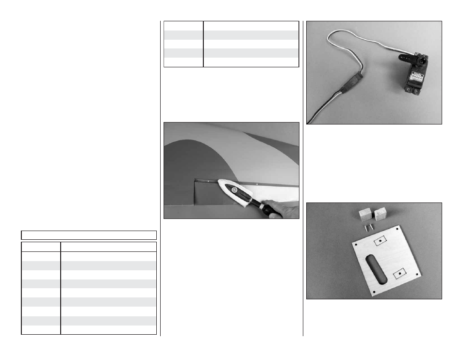
2. Use a covering iron with a covering sock on high
heat to tighten the covering if necessary. Do this for
all of the components of the model. Apply pressure
over sheeted areas to
thoroughly
bond the covering
to the wood.
ASSEMBLE THE WING
Note: Throughout this instruction manual you will be
instructed to use screws to secure different parts. In
all cases, whenever a screw is threaded into wood
sheeting or wood blocks we recommend that you install
the screw and then remove it. Apply a drop of thin CA
glue into the hole to harden the threads. After the glue
has hardened, re-install the screw. Following this step
will insure that you have a solid thread for you screws.
Begin with your right
wing panel
fi rst so your assembly
matches the photos in the manual.
❏
❏
1. Install a 24" [610mm] servo extension to your
aileron servo. Secure it with heat shrink tubing, tape
or other method for securing them together.
❏
❏
2. Install a 12" [305] servo extension to your fl ap
servo. Secure it with heat shrink tubing, tape or other
method for securing them together.
❏
❏
3. Remove the tape holding the
servo covers
to the bottom of the wing. Locate two 5/16" Ч 1/2" Ч
3/4" [8mm × 13mm × 19mm] hardwood blocks. The
markings on the back of the cover are correct for