Top Flite TOPA0210 User Manual
Page 10
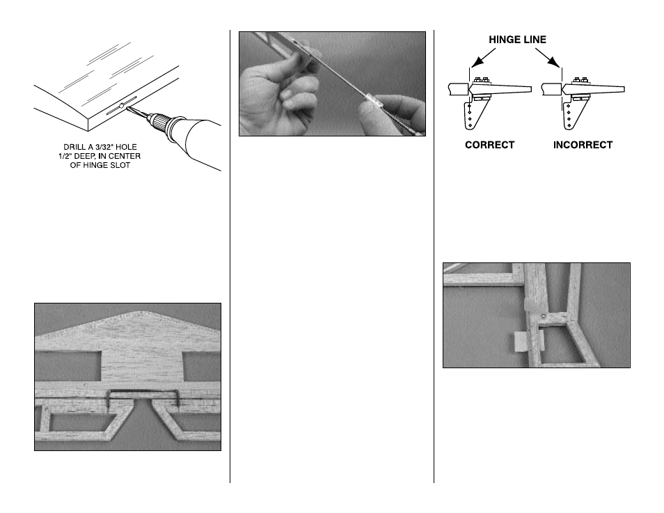
❏ 5. Drill a 3/32" [2.40mm] hole, 1/2" [13mm] deep in
the center of the hinge slots. Use a rotary tool with a
3/32" [2.40 mm] drill bit or a carbide cutter for the
best results. Re-insert your knife blade to clean out
the slot after you drill the hole.
❏ 6. Test fit the elevator halves to the stab with
the hinges.
❏ 7. Position the elevator joiner wire on the trailing
edge of the stab and center it between the elevators.
Mark the LE of both elevators where the joiner will enter.
❏ 8. Cut a slot in the leading edge of both elevator
halves to accommodate the joiner wire. This can be
done easily with the Great Planes “Groove
Tube”™ as shown in the photograph. Hint: If you do
not have a Groove Tube, use a 5/32" [4mm] brass
tube sharpened at one end to cut the slot.
❏ 9. Accurately drill holes in the elevators for the 1/8"
joiner wire. Begin by drilling a 1/16" [1.6mm] pilot
hole. Then drill the final hole to a depth of 7/8"
[22.2mm] with a 9/64" [3.6mm] drill bit. (The hole is
drilled slightly oversize to allow for positioning and to
create a hard epoxy “sleeve” around the wire).
❏ 10. Roughen the joiner wire with coarse sandpaper,
then clean the wire thoroughly with alcohol to remove
any oily residue.
❏ 11. Test fit the joiner wire into the elevators. Then,
glue it in using epoxy. When gluing, lay the elevators
on a flat surface with the LE along a straightedge to
insure perfect alignment. Cover the top of the joined
elevators with a sheet of wax paper. Then, lay a flat,
heavy object on top. A telephone book works well.
This will insure a true flat elevator assembly when
the epoxy cures.
Install the control horns
❏ 1. Place a large control horn at the location
indicated on the elevator plan and rudder plan. Use
a ballpoint pen to mark the location where the holes
need to be drilled.
❏ 2. Check for correct alignment. Drill two 3/32"
[2.4mm] holes for the control horn mounting bolts
through the rudder .
❏ ❏ 3. Repeat step 2 for the right half of the elevator.
❏ 4. Apply a small drop of thin CA in the holes to
harden the wood. Redrill the holes after the CA
has hardened.
❏ 5. Attach the control horn to the left side of the
rudder with two 2-56 x 1/2" [12.7mm] machine
screws.
❏ 6. Attach the control horn to the bottom right side
of the elevator with two 2-56 x 1/2" [12.7mm]
machine screws.
There, that went pretty quick. If your workbench is a
mess, clean it off and get ready to move on to the wing!
10