Toa YA-7000 User Manual
Page 9
9
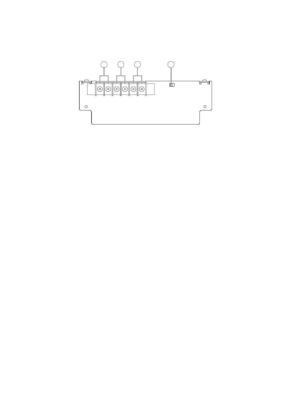
6.2. YA-7000 Amplifier Auto Switching Module (Optional)
[Front]
2
1
3
4
1. Speaker Output Terminal (with cover)
High-impedance, 100V line output for speaker
connections. Signals from the Main Amplifier Input
(2) are output when the main amplifier (i.e. power
amplifier in which the YA-7000 has been mounted)
is operating correctly, and signals from the
Standby Amplifier Input (3) are output if a main
amplifier failure is detected.
(M4 screw terminal; barrier distance: 9 mm)
Note
Never connect this terminal to the speaker output
terminal of the FS-7006PA or FS-7012PA power
amplifier. Failure to follow this instruction could
lead to power amplifier failures.
2. Main Amplifier Input Terminal (with cover)
Connect the main amplifier's speaker output to
this terminal.
(M4 screw terminal; barrier distance: 9 mm)
Note
Only 1 piece of FS-7006PA or FS-7012PA can be
connected to this terminal. Never connect 2 or
more units to this terminal, as the excessive load
could cause the amplifier to fail.
3. Standby Amplifier Input Terminal (with cover)
Connect this terminal to the standby amplifier's
speaker output.
(M4 screw terminal; barrier distance: 9 mm)
Note
Only 1 piece of the FS-7006PA or FS-7012PA can
be connected to this terminal. Never connect 2 or
more units to this terminal, as the excessive load
could cause the amplifier to fail.
4. Operation Mode Selector Switch
Selects the YA-7000's operation mode. Set this
switch to the Normal position in general use.
(Default: Normal)