Tii 90-3 User Manual
Page 2
NOTE: Wires should be aligned to the
corresponding holes. Green wire to the
“T” (GRN) labeled wire guide and the
Red wire to the “R” (RED) labeled wire
guide.
9. Insert wires into wire guides at the same time
until they bottom out.
10. While holding wires in wire guides, terminate
rocker with thumb (lower rocker all the way).
11. Terminate additional pairs to rockers as
required.
12. Assure all rockers are in the down position
and close customer security cover.
13. Test for unit operation.
14. After wiring is complete, close and secure NID
cover (Figure 2).
Installing The 90-3 Sealed Bridging Module
Into A CAC 7600 Network Interface
1. Locate the Network Interface Device.
2. Unlock the cover (similar to Figure 2).
3. Identify the appropriate line position in the
NID.
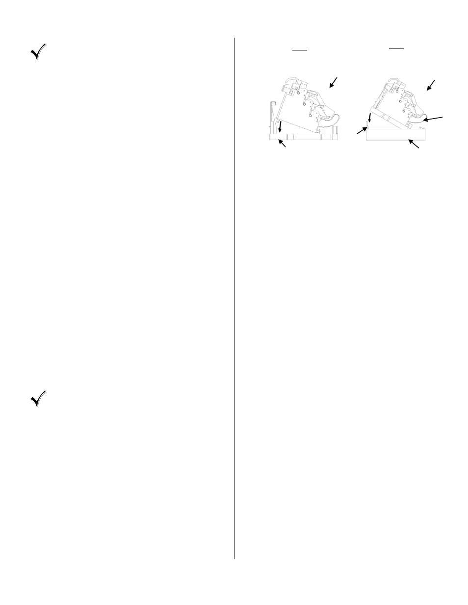
4. Snap the bridging module into the adapter,
then into the base as shown in Figure 4.
5. Terminate wire leads (Tip/Ring) from the
bridging module to terminals on the existing
Customer Bridge Module.
6. Lift all CBM rockers to the open position as
shown (see Figure 1).
7. Hold the customer telephone wires between
thumb and index finger (approx. 1/8”
separation between wires).
NOTE: Wires should be aligned to the
corresponding holes. Green wire to the
“T” (GRN) labeled wire guide and the
Red wire to the “R” (RED) labeled wire
guide.
8. Insert wires into wire guides at the same time
until they bottom out.
9. While holding wires in wire guides, terminate
rocker with thumb (lower rocker all the way).
10. Terminate additional pairs to rockers as
required.
11. Assure all rockers are in the down position
and close customer security cover.
12. Test for unit operation.
13. After wiring is complete, close and secure NID
cover (Figure 2).
STEP 1
Load Bridging Module
Into Adapter
STEP 2
Load Module/Adapter
Assembly Into Base
Of Unit
Adapter
Bridging Module
Adapter
Locking
Bar Tab
CAC 7600 Base
Bridging Module
Figure 4