Tii ADX-FL User Manual
Page 2
Page 2 of 2
P/N 92214201
4. Testing (see Fig 5) - Feeder and subscriber wires
must be segregated between the upper and lower
ports to facilitate isolation testing.
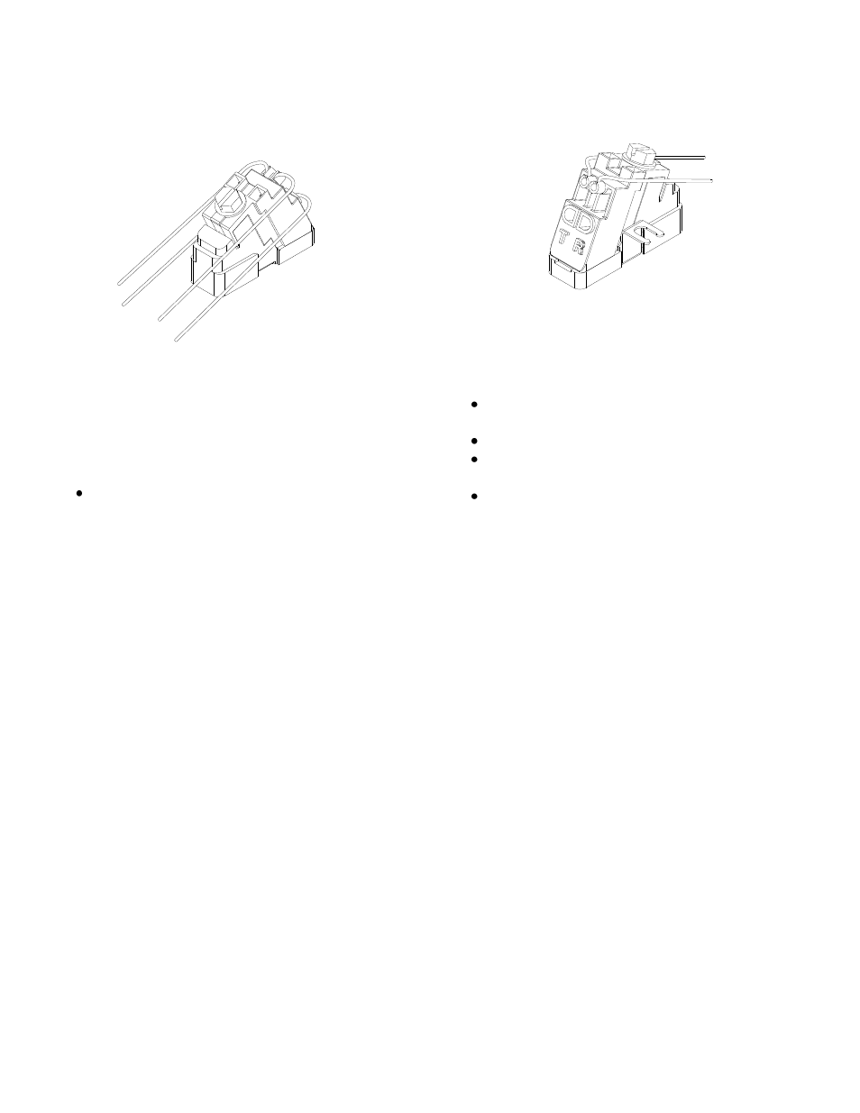
Upper and Lower Port Connected
With Driver in the fully closed position, insert
test clips into tip/ring test port access holes
located at top of driver. Perform customary
continuity tests.
Testing Subscriber Connections (see Fig 6)
Loosen drive screw so driver is in the full
upright position.
Remove telco wires from lower ports of driver.
Tighten drive screw so driver is in the full
down position.
With Driver in the fully closed position, insert
test clips into tip/ring test port access holes
located at top of driver. Perform customary
tests.
Figure 5
Figure 6
- OF025PFNOPNST1 (2 pages)
- IF025PFNOPNST1 (2 pages)
- 210 (2 pages)
- 220 (1 page)
- 231-2 (1 page)
- 68T-2S-4 (1 page)
- 68M-2-1T (1 page)
- 68M-12-1T (1 page)
- 68M-1-1T (1 page)
- 170-06-03 (2 pages)
- 69T (1 page)
- ISB (2 pages)
- ISB-MB (1 page)
- 372S-12LP (1 page)
- 372S-12 (1 page)
- 80-100 (1 page)
- 80-400 (1 page)
- 80-410V-45 (1 page)
- SCT-A (1 page)
- 87 (1 page)
- 95S Series (2 pages)
- 95S Series (3 pages)
- 96-00-1 SERIES (2 pages)
- 96-00-4 SERIES (2 pages)
- 97 (2 pages)
- 97C (1 page)
- 99S SERIES (2 pages)
- 831E (1 page)
- 831W2 (1 page)
- 856E (1 page)
- VIS-4 (2 pages)
- ONT-SS (1 page)
- VIS-2 (2 pages)
- FDT1 Series (2 pages)
- FDT2 Series (2 pages)
- FDH1 (14 pages)
- 169F SERIES (2 pages)
- 506F (2 pages)
- 506F-03 (2 pages)
- 506F-02-01-04 (2 pages)
- 506F-01-01-01/-02/-03 (2 pages)
- UVS-12 (1 page)
- 761-4T-12 (2 pages)
- VIS-3 (2 pages)
- FET1 Series (2 pages)