Tii SVN-12 Series User Manual
Page 2
5.
Lift the blue rocker for the MSO service wires to the full up
position. DO NOT strip wires. (See Figs. 3 & 4)
6.
Insert the MSO service wires from the ATA/EMTA into the
wire guides simultaneously until they bottom-out. While
holding wires in position, terminate into MSO (Blue) rocker
by lowering to the full down terminated position. (See
Figs. 3 & 4)
7.
Lift the Telco rocker to its fully upright position. Insert the
Telco service wires from the service provider into the Red
and Green marked rockers. While the wires are fully
inserted, lower the rocker fully down to complete the Telco
wire termination. (See Figs. 3 & 4)
8.
Terminate the customer wiring onto the Red/Green
marked rocker on the right side of the module. Insert wires
into the customer rocker holes. While assuring that the
wires are fully inserted lower the rocker to its fully seated
position. (See Figs. 3 & 4)
9.
Connect a wire pair designated as Line 2 from the
ATA/EMTA to the rocker labeled TEL (Orange) on the left
side of the module. Follow procedure described above for
the wire pair termination. (See Figs. 3 & 4)
10. Connect customer Telephone line 2 wiring to line 2
(Orange) rocker.
11. To keep wire pairs organized, route them through the
molded wire guides. (See Fig. 3)
12. Repeat termination procedure steps 7 and 8 to terminate
line 2 on module.
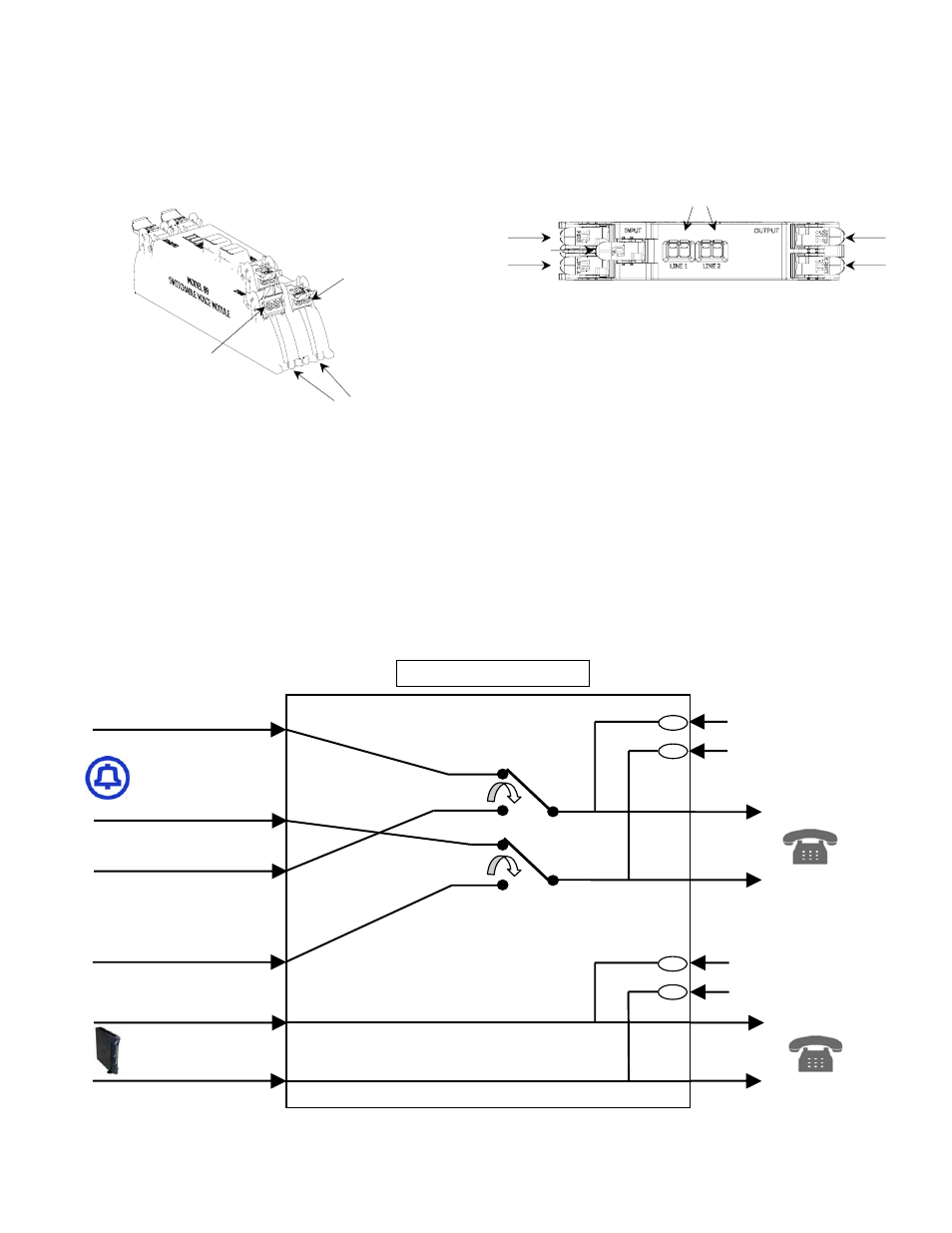
13. Refer to Figure 5 for the 89 module functional schematic.
Figure 3
Terminated rocker
Wire Guides
Full Up Position
Figure 4
Test Points
MSO
Line 2
Telco
Line 2
Customer
Output
Figure 5
Telco Input (Tip)
Telco Input (Ring)
TELCO
MSO
Line 1 (Tip)
Line 1 (Ring)
89 Series
FUNCTIONAL DIAGRAM
MSO Input (Tip)
MSO Input (Ring)
Line 2 (Tip)
Line 2 (Ring)
Line 2 (Tip)
Line 2 (Ring)
Line 2
Test Port (Tip)
Line 2
Test Port (Ring)
Line 1
Test Port (Tip)
Line 1
Test Port (Ring)