Tii SVM-2 Series User Manual
Page 2
tii P/N: 92224401
the green MTA power LED provided on the
line will start to blink.
3.6 Disconnect the customer premise wiring
from the Telephone Network Interface
Device (NID). Straighten the ends of the
wires, cut kinked and stripped ends. Lift the
Green/Red rocker to full up position. Insert
wires into the Customer wire rocker holes.
While assuring that wires are fully inserted
lower the rocker to fully seated position (See
Fig 3).
3.7 Connect the Telco Service using a wire pair
from the Telephone NID to the rocker
labeled TEL (orange). Follow procedure
described above for the wire pair termination
(See Figs 2 & 3).
3.8 To keep wire pairs organized, route them
through the molded wire looms. (See Fig. 2)
4. Installation (Line 2)
4.1 Follow steps 3.4 to 3.8 to connect Line 2
through the SVM-2.
5 RESET
IMPORTANT: This unit MUST be reset during
initial installation. Follow these instructions to
reset the unit.
5.1 Confirm that the power is connected to the
MTA (Blue) rocker of SVM-2 by observing
green LED blinking.
5.2
Gently push the reset button once with a
blunt object to ensure the service to the
customer is from the Telco Service Provider
(See Figure 4).
NOTE:
THE RESET SWITCH IS DISABLED DURING
RINGING VOLTAGE PRESENCE AND TEN
SECONDS AFTER THE LAST RINGING
VOLTAGE.
CAUTION:
TO AVOID PERMANENT DAMAGE TO RESET
BUTTON DO NOT USE EXCESSIVE FORCE
OR A POINTED OBJECT TO ACTIVATE THE
RESET BUTTON.
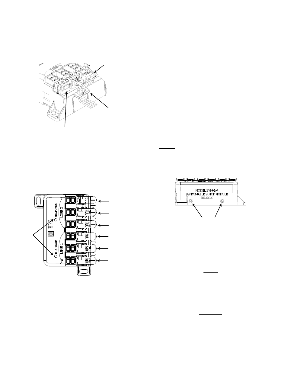
Figure 2
Terminated rocker
Wire loom
Full Up Position
Figure 4
* RESET BUTTON
’S
CUSTOMER WIRING (L1)
TEST POINTS
MTA LED’S
CUSTOMER WIRING (L2)
Figure 3
DIGITAL VOICE
SERVICE WIRES (L2)
TELCO WIRES (L2)
TELCO WIRES
TELCO WIRES (L1)
TELCO WIRES
DIGITAL VOICE
SERVICE WIRES (L1)