Tii 312 Series User Manual
Page 2
Wiring
1. Insert input, output & ground wires through the
grommet as required.
2. Do not strip wire insulation. Make certain wire
ends are cut flush with insulation for all input
and output connections.
3. Unscrew Protector Module Driver Screw to the
full upright position (See Figure 3).
4. Fully insert the two input wires into their
respective tip and ring (color-coded) ports.
5. Insert while holding the two input connection
wires in place. Ensure wires are fully inserted
beyond the IDC connector. Tighten the Drive
Screw to the full down position (See Figure 3).
Pull on wires to ensure proper connection.
Wires should remain securely in place.
6. Lift rocker to the full up position (See Figure
3).
7. Hold the wires between thumb and index
finger (approx. 1/8” separation between wires).
8. Fully insert the output wires into wire their
respective tip and ring (color-coded) ports at
the same time until they bottom out.
9. While holding wires in the wire guides,
terminate rocker by lowering rocker all the
way.
10. Assure the rocker is in the down position (See
Figure 3). Pull on wires to ensure proper
connection. Wires should remain securely
in place.
11. Unscrew the ground screw and insert the
ground wire into the grounding retainer post.
Once inserted, tighten the ground screw to
hold the ground wire firmly in place (See
Figure 3). Be sure the other end is attached to
an appropriate ground source.
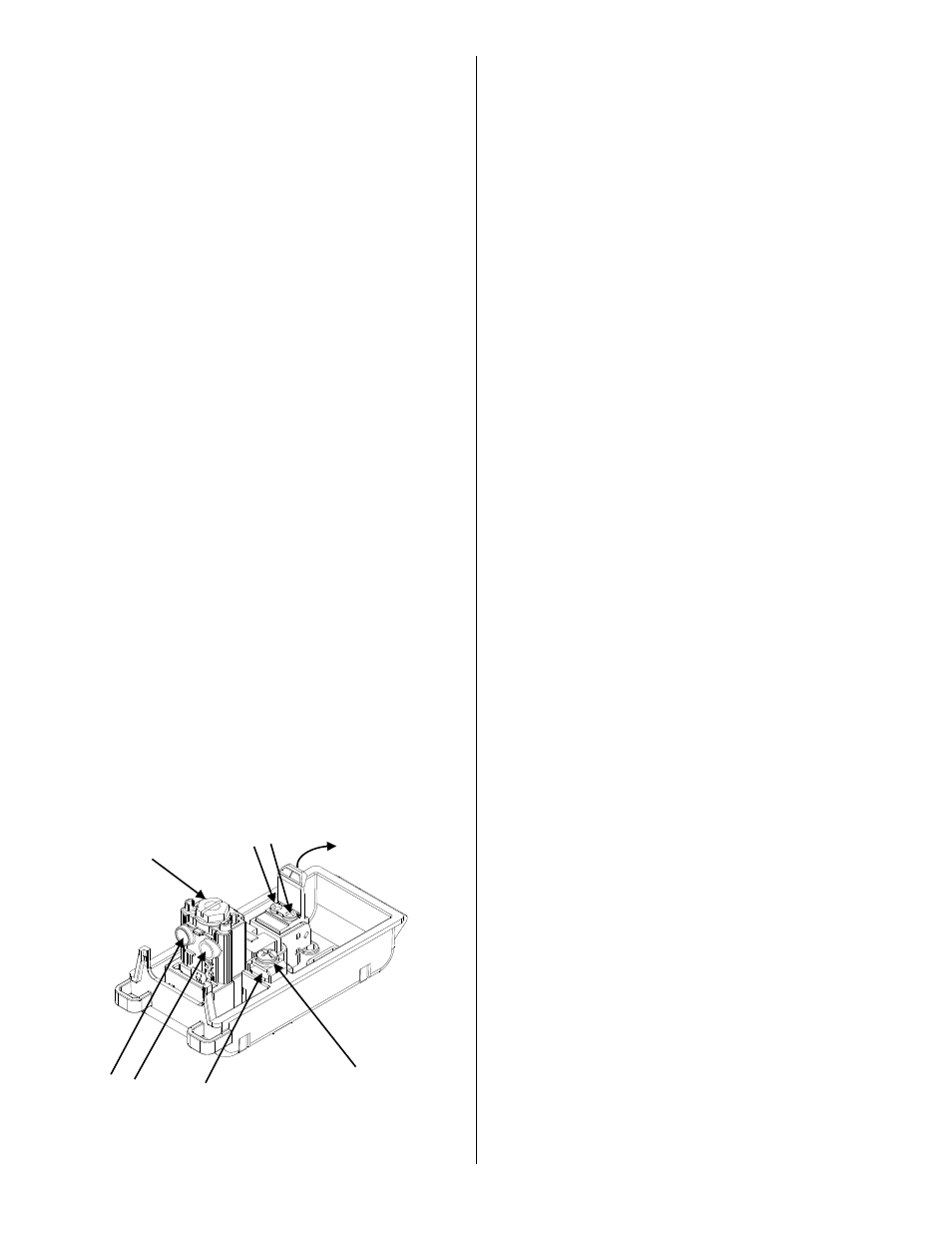
Figure 3
Testing
1. Insert test probes into test ports (See Figure 2)
to check for dial tone.
Drive Screw
– open to
insert wires- close to
terminate wires
Insert ground
wire here
Ground Screw
Insert input
wires here
Insert output
wires here
Rocker
– open to
insert wires- close
to terminate wires