Tii 91 Series User Manual
Tii Equipment
P/N 92215701 • Rev C•
4/1/2008
Warranty: If this unit fails during the warranty period, contact tii customer service to authorize return. Unit may be returned prepaid.
Model tii 91 Series
Expansion Modules
Installation Note
Description
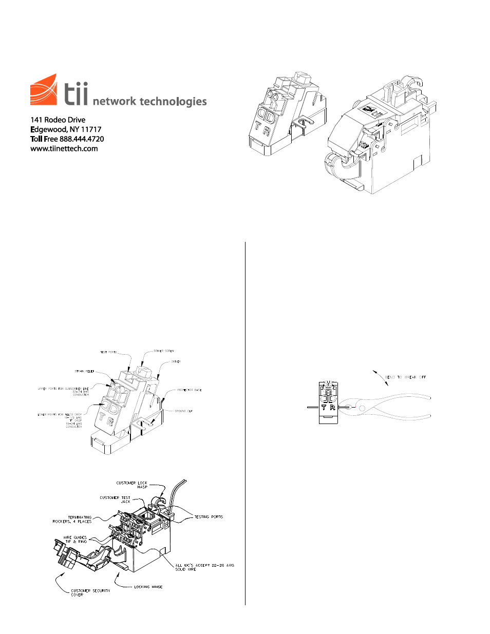
1. The tii 91 Series Expansion Modules consist
of a single station protector and a customer
bridge module required to upgrade or expand
subscriber lines within a tii Network Interface
Device (NID). They are available with either
traditional binding post terminations or gel-
sealed IDC terminations.
Features
Figure 1
Figure 2
Installation
Installing the Protector
1. The Angle Driver (Sealed IDC Protector) is
delivered with a universal grounding and
mounting tab (See Figure 1). If installing a
new module into a NID, break away the
unwanted ground tab from the module using a
pair of pliers and discard (See Figure 3).
Binding post protectors do not require this
step. Simply Install the module on desired
NID ground post and secure with washer and
nut.
Figure 3
Wiring
Angle Driver Sealed IDC Protector
1. The two upper ports of the Angle Driver are
intended to terminate subscriber (customer)
wires. Telco drop (feeder) wires must be
terminated in the two lower ports of the Angle
Driver.
2. Upper Port Subscriber Connections
(See Figure 4)
Subscriber terminations are already made in
the factory. If it is necessary to re-terminate a
subscriber wire, do so as follows:
2a. Do not strip wire insulation. Make certain
wire ends are cut flush with insulation.
NOTE: RJ-11 PLUG IS
NOT REQUIRED FOR
NORMAL OPERATION.