Tii 8925 Series User Manual
Page 2
4.
Tools and Equipment
The normal complement of mechanical
tools is recommended for mounting and wiring
the unit.
5.
Mounting
Using an 89B bracket, simply snap the
8925 Series INI on to the bracket (Figure 3).
FIGURE 3
6.
Telco Wiring
6.1
The 8925 Series INI is provided with an
RJ-21 connector on the rear of the unit. Telco
connection is made by means of a 25-pair
wired standard male connector that is secured
to the back of the unit with the provided hook-
and-loop strap (Figure 4).
FIGURE 4
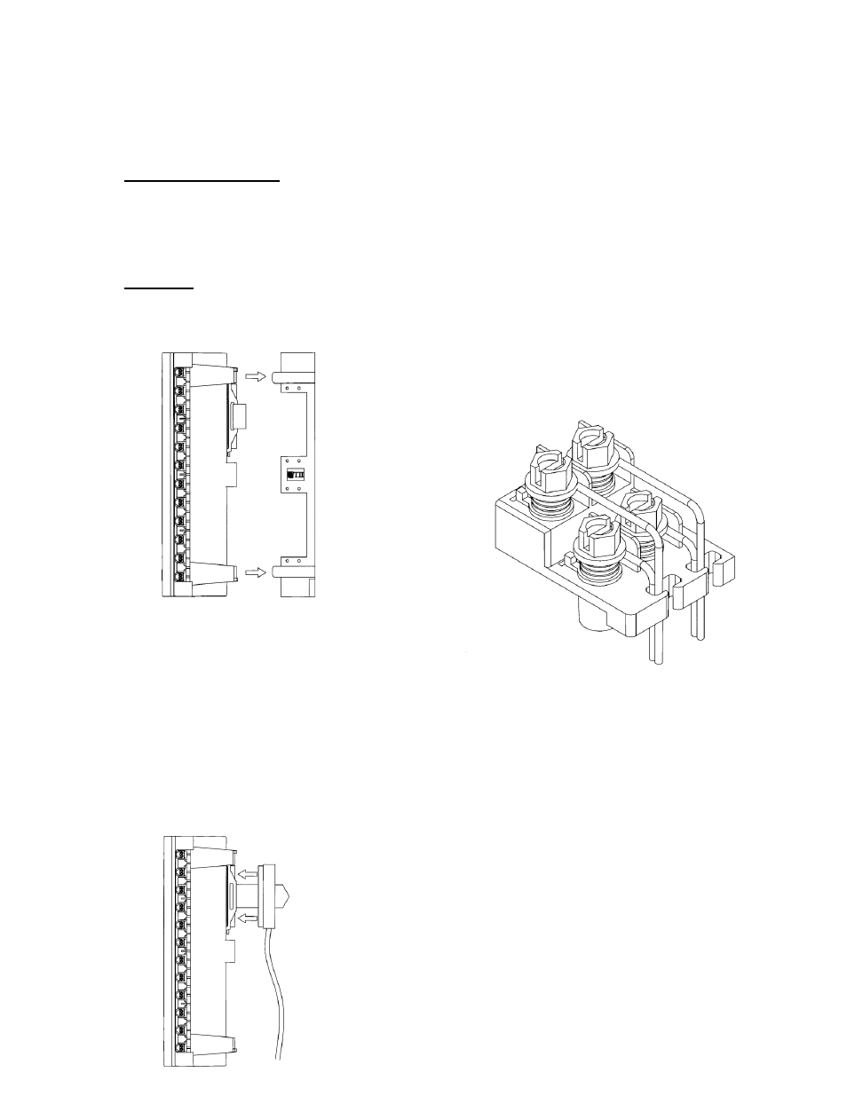
7.
Subscriber Wiring
– Screw Terminal
Version
– 8925B Series (Figure 1)
7.1
Open the orange cover and temporarily
disconnect the subscriber wiring by inserting an
RJ-11 plug in the jack at the location you will be
wiring.
7.2
Route subscriber wires through the wire
rungs attached to the subscriber bridge you will
be using. Strip off about ½ inch of insulation
from each wire (see Figure 7).
7.3
Loosen the terminal screws about one
turn and wrap the stripped wires under them
–
between the washers. Match wires, color-to-
color (example: red wire to terminal post
marked red, or a letter “R, green wire to a ter-
minal post marked green or “G” and so on).
Retighten the terminal screws (see Figure 7).
7.4
Remove the temporary inserted RJ-11
plug from the modular plug.
7.5
Use approved practices to test the line.
8.
Subscriber Wiring
– IDC Terminals
(Figure 2)
Open the orange cover and temporarily dis-
connect the subscriber wiring by inserting RJ-
FIGURE 7